Fractography
| Part of a series on |
| Forensic science |
|---|
 |
Fractography is the study of the fracture surfaces of materials. Fractographic methods are routinely used to determine the cause of failure in engineering structures, especially in product failure and the practice of forensic engineering or failure analysis. In material science research, fractography is used to develop and evaluate theoretical models of crack growth behavior.
One of the aims of fractographic examination is to determine the cause of failure by studying the characteristics of a fractured surface. Different types of crack growth (e.g. fatigue, stress corrosion cracking, hydrogen embrittlement) produce characteristic features on the surface, which can be used to help identify the failure mode. The overall pattern of cracking can be more important than a single crack, however, especially in the case of brittle materials like ceramics and glasses.
Usage
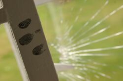
Fractography is a widely used technique in forensic engineering, forensic materials engineering and fracture mechanics to understand the causes of failures and also to verify theoretical failure predictions with real life failures. It is of use in forensic science for analysing broken products which have been used as weapons, such as broken bottles for example. Thus a defendant might claim that a bottle was faulty and broke accidentally when it impacted a victim of an assault. Fractography could show the allegation to be false, and that considerable force was needed to smash the bottle before using the broken end as a weapon to deliberately attack the victim. Bullet holes in glass windscreens or windows can also indicate the direction of impact and the energy of the projectile. In these cases, the overall pattern of cracking is vital to reconstructing the sequence of events, rather than the specific characteristics of a single crack. Fractography can determine whether a cause of train derailment was a faulty rail, or if a wing of a plane had fatigue cracks before a crash.
Fractography is used also in materials research, since fracture properties can correlate with other properties and with structure of materials.
Feature identification
Origin
An important aim of fractography is to establish and examine the origin of cracking, as examination at the origin may reveal the cause of crack initiation. Initial fractographic examination is commonly carried out on a macro scale utilising low power optical microscopy and oblique lighting techniques to identify the extent of cracking, possible modes and likely origins. Optical microscopy or macrophotography are often enough to pinpoint the nature of the failure and the causes of crack initiation and growth if the loading pattern is known.
Common features that may cause crack initiation are inclusions, voids or empty holes in the material, contamination, and stress concentrations.
Fatigue crack growth
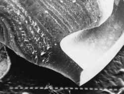
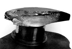
The image of a broken crankshaft shows the component failed from a surface defect near the bulb at lower centre. The semi-circular marks near the origin indicate a crack growing up into the bulk material by process known as fatigue. The crankshaft also shows hachures, which are the lines on fracture surfaces that can be traced back to the origin of the fracture. Some modes of crack growth can leave characteristic marks on the surface that identify the mode of crack growth and origin on a macro scale e.g. beachmarks or striations on fatigue cracks.
Microscopy
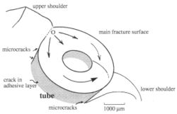
Microscopes can be used to determine the initiation point and the mechanism that caused crack growth. The information can be obtained from images of the fracture surface known as fractographs and used in constructing diagrams. A schematic fracture surface map can be used to isolate and identify the features on the surface which show how the product failed. Such a map can be a valuable way of presenting information which shows clearly how a crack was initiated which grew with time.
USB Microscopy
USB microscopes are especially useful for examining fracture surface features since they are small enough to be hand-held. A variety of camera sizes and resolution are available commercially at low cost. The camera cable plugs into the computer via a USB plug and most such devices come with illumination at the camera supplied by LED lights.
Scanning electron microscopy
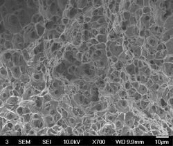
In many cases, fractography requires examination at a finer scale, which is usually carried out in a scanning electron microscope or SEM. The resolution is much higher than the optical microscope, although samples are examined in a partial vacuum and colour is absent. Improved SEM's now allow examination at near atmospheric pressures, so allowing examination of sensitive materials such as those of biological origin. The SEM is especially useful when combined with Energy dispersive X-ray spectroscopy or EDX, which can be performed in the microscope, so very small areas of the sample can be analysed for their elemental composition.
Example
Breast implant
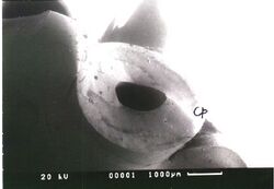
A cusp is formed where brittle cracks meet, as shown on the picture of a failed catheter (Cp). The cusp was formed by brittle failure of the catheter on a breast implant in silicone rubber. The origin of the cracks is at the shoulder at the left-hand side. Identifying such features will allow a fracture surface map to be made of the surface being studied. The implant failed because of overload, all the imposed loads being concentrated at the connection between the catheter and the bag holding salt solution. As a result, the patient reported loss of fluid from the implant, and it was extracted surgically and replaced.
In the case of the failed breast implant catheter, the crack path was very simple, but the cause more subtle. Further scanning electron microscopy showed numerous microcracks between the bag and the catheter, indicating that the adhesive bond between the two components had failed prematurely, perhaps through faulty manufacture. The material of construction of both bag and catheter, silicone rubber is a physically weak elastomer, and product design must allow for the low tear or shear strength of the material.
Maritime Patrol Aircraft
A non-critical crack occurred in the fastener hole of a lower wing plank. The plank was made from a 3.2 mm thick AA7075-T6 aluminium alloy. The time of the detection of the crack and the aircraft's counting g-meter allowed investigators to find out the load on the aircraft from use. The cracks on an SEM showed evidence and patterns of fatigue. The cyclic load and fatigue appeared to have progressively gone worse with some cracks being large and others being small in length and width indicating occasional force stronger than 2> g's. The g-meter showed that the aircraft had flown 2,500 flights, with the g force and acceleration occasionally exceeding more than 2 G's. This was more than the maximum advertised for the manufacturer.[1] The conclusion was that fatigue and cracks should be inspected regularly on old or commonly used aircraft.[1] The study also found novel ways for Quantitative fractography to be used on aircraft, which compares load history (in this case the g-meter) and records of the alloy experiencing fatigue in a lab setting with different pressure, cycles, and temperatures. The study used the database of cracks to create a model that predicts forces and crack progression.
See also
- Conchoidal fracture
- Fatigue (material)
- Failure analysis
- Forensic engineering
- Forensic materials engineering
- Fracture
- Forensic polymer engineering
- Forensic science
References
- ↑ 1.0 1.1 Goldsmith, N. T.; Wanhill, R. J. H.; Molent, L. (2019-02-01). "Quantitative fractography of fatigue and an illustrative case study" (in en). Engineering Failure Analysis 96: 426–435. doi:10.1016/j.engfailanal.2018.10.013. ISSN 1350-6307. https://www.sciencedirect.com/science/article/pii/S1350630718300852.
- Lewis, Peter Rhys, Reynolds, K, and Gagg, C, Forensic Materials Engineering: Case studies, CRC Press (2004).
- Mills, Kathleen Fractography, American Society of Metals (ASM) handbook, volume 12 (1991).
- N.T. Goldsmith, R.J.H. Wanhill, L. Molent, Quantitative fractography of fatigue and an illustrative case study, Engineering Failure Analysis, volume 96 (February 2019) Pages 426–435.
 |
