Electronic mixer
An electronic mixer is a device that combines two or more electrical or electronic signals into one or two composite output signals. There are two basic circuits that both use the term mixer, but they are very different types of circuits: additive mixers and multiplicative mixers. Additive mixers are also known as "analog adders" to distinguish from the related digital adder circuits.
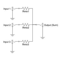
Simple additive mixers use Kirchhoff's circuit laws to add the currents of two or more signals together, and this terminology ("mixer") is only used in the realm of audio electronics where audio mixers are used to add together audio signals such as voice signals, music signals, and sound effects.
Multiplicative mixers multiply together two time-varying input signals instantaneously (instant-by-instant). If the two input signals are both sinusoids of specified frequencies f1 and f2, then the output of the mixer will contain two new sinusoids that have the sum f1 + f2 frequency and the difference frequency absolute value |f1 - f2|.
Any nonlinear electronic block driven by two signals with frequencies f1 and f2 would generate intermodulation (mixing) products. A multiplier (which is a nonlinear device) will generate ideally only the sum and difference frequencies, whereas an arbitrary nonlinear block will also generate signals at 2·f1-3·f2, etc. Therefore, normal nonlinear amplifiers or just single diodes have been used as mixers, instead of a more complex multiplier. A multiplier usually has the advantage of rejecting – at least partly – undesired higher-order intermodulations and larger conversion gain.
Additive mixers
Additive mixers add two or more signals, giving out a composite signal that contains the frequency components of each of the source signals. The simplest additive mixers are resistor networks, and thus purely passive, while more complex matrix mixers employ active components such as buffer amplifiers for impedance matching and better isolation.
Multiplicative mixers
An ideal multiplicative mixer produces an output signal equal to the product of the two input signals. In communications, a multiplicative mixer is often used together with an oscillator to modulate signal frequencies. A multiplicative mixer can be coupled with a filter to either up-convert or down-convert an input signal frequency, but they are more commonly used to down-convert to a lower frequency to allow for simpler filter designs, as done in superheterodyne receivers. In many typical circuits, the single output signal actually contains multiple waveforms, namely those at the sum and difference of the two input frequencies and harmonic waveforms. The output signal may be obtained by removing the other signal components with a filter.í
Mathematical treatment
The received signal can be represented as
- [math]\displaystyle{ E_\mathrm{sig} \cos(\omega_\mathrm{sig}t+\varphi)\, }[/math]
and that of the local oscillator can be represented as
- [math]\displaystyle{ E_\mathrm{LO} \cos(\omega_\mathrm{LO}t).\, }[/math]
For simplicity, assume that the output I of the detector is proportional to the square of the amplitude:
- [math]\displaystyle{ I\propto \left( E_\mathrm{sig}\cos(\omega_\mathrm{sig}t+\varphi) + E_\mathrm{LO}\cos(\omega_\mathrm{LO}t) \right)^2 }[/math]
- [math]\displaystyle{ =\frac{E_\mathrm{sig}^2}{2}\left( 1+\cos(2\omega_\mathrm{sig}t+2\varphi) \right) }[/math]
- [math]\displaystyle{ + \frac{E_\mathrm{LO}^2}{2}(1+\cos(2\omega_\mathrm{LO}t)) }[/math]
- [math]\displaystyle{ + E_\mathrm{sig}E_\mathrm{LO} \left[ \cos((\omega_\mathrm{sig}+\omega_\mathrm{LO})t+\varphi) + \cos((\omega_\mathrm{sig}-\omega_\mathrm{LO})t+\varphi) \right] }[/math]
- [math]\displaystyle{ =\underbrace{\frac{E_\mathrm{sig}^2+E_\mathrm{LO}^2}{2}}_{constant\;component}+\underbrace{\frac{E_\mathrm{sig}^2}{2}\cos(2\omega_\mathrm{sig}t+2\varphi) + \frac{E_\mathrm{LO}^2}{2}\cos(2\omega_\mathrm{LO}t) + E_\mathrm{sig}E_\mathrm{LO} \cos((\omega_\mathrm{sig}+\omega_\mathrm{LO})t+\varphi)}_{high\;frequency\;component} }[/math]
- [math]\displaystyle{ + \underbrace{E_\mathrm{sig}E_\mathrm{LO} \cos((\omega_\mathrm{sig}-\omega_\mathrm{LO})t+\varphi)}_{beat\;component}. }[/math]
The output has high frequency ([math]\displaystyle{ 2\omega_\mathrm{sig} }[/math], [math]\displaystyle{ 2\omega_\mathrm{LO} }[/math] and [math]\displaystyle{ \omega_\mathrm{sig}+\omega_\mathrm{LO} }[/math]) and constant components. In heterodyne detection, the high frequency components and usually the constant components are filtered out, leaving the intermediate (beat) frequency at [math]\displaystyle{ \omega_\mathrm{sig}-\omega_\mathrm{LO} }[/math]. The amplitude of this last component is proportional to the amplitude of the signal radiation. With appropriate signal analysis the phase of the signal can be recovered as well.
If [math]\displaystyle{ \omega_\mathrm{LO} }[/math] is equal to [math]\displaystyle{ \omega_\mathrm{sig} }[/math] then the beat component is a recovered version of the original signal, with the amplitude equal to the product of [math]\displaystyle{ E_\mathrm{sig} }[/math] and [math]\displaystyle{ E_\mathrm{LO} }[/math]; that is, the received signal is amplified by mixing with the local oscillator[clarification needed]. This is the basis for a Direct conversion receiver.
Implementations
Multiplicative mixers have been implemented in many ways. The most popular are Gilbert cell mixers, diode mixers, diode ring mixers (ring modulation) and switching mixers. Diode mixers take advantage of the non-linearity of diode devices to produce the desired multiplication in the squared term. They are very inefficient as most of the power output is in other unwanted terms which need filtering out. Inexpensive AM radios still use diode mixers.
Electronic mixers are usually made with transistors and/or diodes arranged in a balanced circuit or even a double-balanced circuit. They are readily manufactured as monolithic integrated circuits or hybrid integrated circuits. They are designed for a wide variety of frequency ranges, and they are mass-produced to tight tolerances by the hundreds of thousands, making them relatively cheap.
Double-balanced mixers are very widely used in microwave communications, satellite communications, ultrahigh frequency (UHF) communications transmitters, radio receivers, and radar systems.
Gilbert cell mixers are an arrangement of transistors that multiplies the two signals.
Switching mixers use arrays of field-effect transistors or vacuum tubes. These are used as electronic switches, to alternate the signal direction. They are controlled by the signal being mixed. They are especially popular with digitally controlled radios. Switching mixers pass more power and usually insert less distortion than Gilbert cell mixers.
da:Lydmikser ja:ミキサー pl:Mieszacz
This article does not cite any external source. HandWiki requires at least one external source. See citing external sources. (2021) (Learn how and when to remove this template message) |
 |


