Engineering:Outside plant

In telecommunication, the term outside plant has the following meanings:
- In civilian telecommunications, outside plant refers to all of the physical cabling and supporting infrastructure (such as conduit, cabinets, tower or poles), and any associated hardware (such as repeaters) located between a demarcation point in a switching facility and a demarcation point in another switching center or customer premises.[1]
- In the United States, the DOD defines outside plant as the communications equipment located between a main distribution frame (MDF) and a user end instrument.[1]
The CATV industry divides its fixed assets between head end or inside plant, and outside plant. The electrical power industry also uses the term outside plant to refer to electric power distribution systems.
Context


Network connections between devices such as computers, printers, and phones require a physical infrastructure to carry and process signals. Typically, this infrastructure will consist of:
- Cables from wall outlets and jacks run to a communications closets, sometimes referred to as station cable.
- Cables connecting one communications closet to another, sometimes referred to as riser cable.
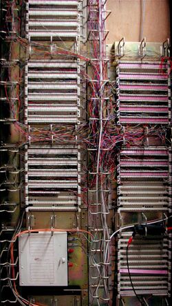
- Racks containing telecommunications hardware, such as switches, routers, and repeaters.
- Cables connecting one building to another.
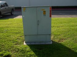
- Exterior communications cabinets containing hardware outside of buildings.
- Radio transceivers used inside or outside buildings, such as wireless access points, and hardware associated with them, such as antennas and towers.
The portion of this infrastructure contained within a building is the inside plant, and the portion of this infrastructure connecting buildings or facilities is the outside plant. Where these two plants meet in a given structure is the demarcation point.
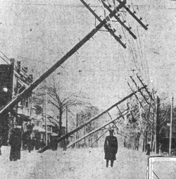
Outside plant cabling, whether copper or fiber, is generally installed as aerial cable between poles, in an underground conduit system, or by direct burial.[2] Hardware associated with the outside plant must be either protected from the elements (for example, distribution frames are generally protected by a street side cabinet) or constructed with materials suitable for exposure to the elements. Installation of the outside plant elements often require construction of significant physical infrastructure, such as underground vaults.[3] In older large installations, cabling is sometimes protected by air pressure systems designed to prevent water infiltration. While this is not a modern approach, the cost of replacement of the older cabling with sealed cabling is often prohibitively expensive.[4] The cabling used in the outside plant must also be protected from electrical disturbances caused by lightning or voltage surges due to electrical shorts or induction.[5]
Example: copper access network
In civilian telecommunications, the copper access network (also known as the local loop) providing basic telephone or DSL services typically consists of the following elements:[6]
- In-house wiring that connects customer premises equipment to the demarcation point, usually in residential installations contained in a weather protected box.
- One or more twisted pairs, called a drop wire. The drop wires typically connect to a splice case, located in line for aerial cables, or in a small weather protected case for underground wiring, where the local cabling is connected to a secondary feeder line. These cables contain fifty or more twisted pairs.
- Secondary feeder lines run to a streetside cabinet containing a distribution frame called a Serving Area Interface (SAI).
- The SAI is connected to the main distribution frame, located at a Telephone exchange or other switching facility, by one or more primary feeder lines which contain hundreds of copper twisted pairs. An SAI may also contain a Digital subscriber line access multiplexer (DSLAM) supporting DSL service.
Active equipment (such as a POTS or DSL line circuit) can then be connected to the line in order to provide service, but this is not considered part of outside plant.
Protecting equipment in the outside plant
The environment can play a large role in the quality and lifespan of equipment used in the outside plant. It is critical that environmental testing criteria as well as design and performance requirements be defined for this type of equipment.
There are generally four operating environments or classes covering all outside plant (OSP) applications, including wireless facilities.
- Class 1: Equipment in a Controlled Environment
- Class 2: Protected Equipment in Outside Environments
- Class 3: Protected Equipment in Severe Outside Environments
- Class 4: Products in an Unprotected Environment
Electronic equipment located in one or more of these environmental class locations is designed to withstand various environmental operating conditions resulting from climatic conditions that may include rain, snow, sleet, high winds, ice, salt spray, and sand storms. Since outside temperatures can possibly range from −40 °C (−40 °F) to 46 °C (115 °F), with varying degrees of solar loading, along with humidity levels ranging from below 10% up to 100%, significant environmental stresses within the enclosure or facility can be produced.
Telcordia GR-3108, Generic Requirements for Network Equipment in the Outside Plant (OSP), contains the most recent industry data regarding each Class described above. It also discusses what is currently happening in ATIS and Underwriters Laboratories (UL).
The document also includes
- Environmental criteria such as operating temperatures, humidity, particulate contamination, pollution exposure, and heat dissipation
- Mechanical criteria such as structural requirements, packaging, susceptibility to vibration, earthquake, and handling
- Electrical protection and safety including protection from lightning surges, AC power induction and faults, and Electromagnetic Interference (EMI), and DC power influences
Handholes and other below-ground splice vaults
Handholes and other below-ground splice vaults house telecommunications components used in an Outside Plant (OSP) environment.
Handholes are plastic or polymer concrete structures set below ground with their lids flush to the surrounding soil, turf, footpath, or road surface. They can be used to house and protect copper, coaxial, and optical fiber telephone cable splices and distribution elements. They safeguard and provide convenient access to cable termination and branch points, provide flexibility and access for installation operations (e.g., pulling or blowing cables), provide mechanical and environmental protection for splices, allow access for craftsperson work activities, and discourage access by unauthorized persons.
Handholes and other below-ground splice vaults are deployed in a variety of environments. The major distinctions in these environments focus on the strength and frequency of vehicular and foot traffic loading. There are four basic application environments:
- Light Duty: Pedestrian Only
- Medium Duty: Pedestrian and Light Incidental Vehicular Traffic (Up to Class 5 Vehicles)
- Heavy Duty: Non-Deliberate (Incidental) Vehicular Traffic (Up to Class 7 Vehicles)
- Heavy Duty: Non-Deliberate (Incidental) Vehicular Traffic (Up to Class 8 Vehicles)
Handhole-type products deployed in any environment are subjected to the following types of traffic loading: Vertical Cover Load, Vertical Sidewall Load, Lateral Sidewall Load, and Long-Term Lateral Sidewall Load.
Telcordia GR-902, Generic Requirements for Handholes and Other Below-Ground Splice Vaults, contains detailed industry requirements for handholes, and includes specific loading requirements for the defined application environments. It provides explicit correlations to other standards such as ANSI/SCTE-77,[7] AASHTO[8] specifications, and ASTM C857.[9]
Corrosion resistance
Corrosion in outside plant telecommunications network components is caused by exposure to the effects of temperature, humidity, electrical power, and contaminants. Corrosion resistance criteria for these network components are based on the environments to which they are exposed.
Outside plant environments can be above-ground, underground, buried, or underwater. Industry requirements document Telcordia GR-2836 defines these environments and provides corrosion resistance criteria for the telecommunications equipment in each.[10] It also includes references to various associated ASTM Standards.
Above-ground plant
Above-ground plant includes all the telecommunications equipment physically located on or above the ground. This includes enclosures such as huts, cabinets, and pedestals, and the equipment mounted therein. It also includes pole-mounted equipment and cases, and pole-line hardware.
Above-ground plant can be exposed to extreme temperatures, and to humidity that varies with the seasons and with daily temperature changes. When humidity condenses on the surfaces of outdoor apparatus or equipment, the corrosivity of the moisture layer can be increased by industrial pollutants that render the condensate moisture corrosive. In sea coastal areas, wind-borne, salt-laden water droplets can deposit on exposed components.
Near large cultivated areas, where fertilizers are applied by airplanes, the wind may carry nitrates, phosphates, and ammonium compounds to settle on metallic components of the above-ground telephone plant. Similarly, in residential areas, lawn fertilizers and herbicides can cause corrosion. In regions with snow, the salts used to melt snow and ice on roadways can accelerate corrosion. Under extreme conditions, pedestals and cabinets may be flooded with water that contains mud and corrosive salts. Corrosion of these flooded components may be accelerated by the presence of dc voltages used to power the networks. Secretions from insects can also accelerate corrosion. Finally, chewing by rodents may expose metallic components, normally protected by a polymer or paint coating, to a corrosive environment.
Underground plant
Underground plant includes all the telecommunications equipment installed in underground structures such as utility holes, Controlled Environment Vaults (CEVs), and ducts, along with associated hardware. Underground plant can be exposed to waters containing water-soluble salts of the native soil. Utility holes often show evidence of corrosion of support hardware and bonding ribbons that is caused by sulfate-reducing bacteria. The environment in utility holes and ducts can be made corrosive by man-made chemicals such as industrial effluent, fertilizers, and de-icing salts. Protective plastic coatings and cable jackets can rapidly deteriorate from leaking steam pipes present in many urban areas and from gasoline leaking from underground storage tanks.
The most aggressive contributor to corrosion of underground plant is dc stray current from electrified rail transportation systems, cathodic protection rectifiers, or welding and mining operations. Although such dc currents are mostly dealt with “after the fact” using protective systems (e.g., low resistance bonds, reverse current switches, cathodic protection), some of the protection has to be included at the manufacturing stage. This protection may include insulating covers on cable shields, or nonmetallic components or coatings for apparatus.
Buried plant
Buried plant consists of telecommunications equipment such as cables, splice closures, lower parts of pedestals, and grounding systems directly buried in the soil. Buried plant can be exposed to the same corrosive environment as underground plant. In addition, attack by gophers can expose underlying components to corrosion attack.
Underwater plant
Underwater plant includes all telecommunications equipment located beneath the surface of a body of water. This includes cables and repeaters. The water can range from relatively pure, to brackish, to badly contaminated with industrial effluent.
See also
References
- ↑ 1.0 1.1 "Telecommunications: Glossary of Telecommunication Terms". http://www.its.bldrdoc.gov/fs-1037/fs-1037c.htm.
- ↑ "Outside Plant Cabling". http://ecmweb.com/mag/electric_outside_plant_cabling/.
- ↑ "Preparing for Outside Plant Installation". http://www.ecmag.com/?fa=article&articleID=10340.
- ↑ "Understand Air Pressure Systems for OSP Cabling". http://ecmweb.com/mag/electric_understanding_air_pressure/index.html.
- ↑ "Protecting Your Assets with Bonding and Grounding". http://ecmweb.com/mag/electric_protecting_assets_bonding/index.html.
- ↑ "Outside Plant: Basic Elements". http://www.privateline.com/OSP/No.html.
- ↑ ANSI/SCTE-77, Specification for Underground Enclosure Integrity
- ↑ American Association of State Highway and Transportation Officials (AASHTO)
- ↑ American Society for Testing and Materials (ASTM) C857, Standard Practice for Minimum Structural Design Loading for Underground Precast Concrete Utility Structures
- ↑ GR-2836-CORE, Generic Requirements for Assuring Corrosion Resistance of Telecommunication Equipment in the Outside Plant, Telcordia.
 |
