Engineering:Stroboscope


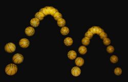
A stroboscope, also known as a strobe, is an instrument used to make a cyclically moving object appear to be slow-moving, or stationary. It consists of either a rotating disk with slots or holes or a lamp such as a flashtube which produces brief repetitive flashes of light. Usually, the rate of the stroboscope is adjustable to different frequencies. When a rotating or vibrating object is observed with the stroboscope at its vibration frequency (or a submultiple of it), it appears stationary. Thus stroboscopes are also used to measure frequency.
The principle is used for the study of rotating, reciprocating, oscillating or vibrating objects. Machine parts and vibrating string are common examples. A stroboscope used to set the ignition timing of internal combustion engines is called a timing light.
Mechanical
In its simplest mechanical form, a stroboscope can be a rotating cylinder (or bowl with a raised edge) with evenly spaced holes or slots placed in the line of sight between the observer and the moving object. The observer looks through the holes/slots on the near and far side at the same time, with the slots/holes moving in opposite directions. When the holes/slots are aligned on opposite sides, the object is visible to the observer.
Alternately, a single moving hole or slot can be used with a fixed/stationary hole or slot. The stationary hole or slot limits the light to a single viewing path and reduces glare from light passing through other parts of the moving hole/slot.
Viewing through a single line of holes/slots does not work, since the holes/slots appear to just sweep across the object without a strobe effect.
The rotational speed is adjusted so that it becomes synchronised with the movement of the observed system, which seems to slow and stop. The illusion is caused by temporal aliasing, commonly known as the stroboscopic effect.
Electronic
In electronic versions, the perforated disc is replaced by a lamp capable of emitting brief and rapid flashes of light. Typically a gas-discharge or solid-state lamp is used, because they are capable of emitting light nearly instantly when power is applied, and extinguishing just as fast when the power is removed.
By comparison, incandescent lamps have a brief warm-up when energized, followed by a cool-down period when power is removed. These delays result in smearing and blurring of detail of objects partially illuminated during the warm-up and cool-down periods. For most applications, incandescent lamps are too slow for clear stroboscopic effects. Yet when operated from an AC source they are mostly fast enough to cause audible hum (at double mains frequency) on optical audio playback such as on film projection.
The frequency of the flash is adjusted so that it is an equal to, or a unit fraction of the object's cyclic speed, at which point the object is seen to be either stationary or moving slowly backward or forward, depending on the flash frequency.
Neon lamps or light-emitting diodes are commonly used for low-intensity strobe applications, Neon lamps were more common before the development of solid-state electronics, but are being replaced by LEDs in most low-intensity strobe applications.
Xenon flash lamps are used for medium- and high-intensity strobe applications. Sufficiently rapid or bright flashing may require active cooling such as forced-air or water cooling to prevent the xenon flash lamp from melting.
History


Joseph Plateau of Belgium is generally credited with the invention of the stroboscope in 1832, when he used a disc with radial slits which he turned while viewing images on a separate rotating wheel. Plateau's device became known as the "Phenakistoscope". There was an almost simultaneous and independent invention of the device by the Austrian Simon Ritter von Stampfer, which he named the "Stroboscope", and it is his term which is used today. The etymology is from the Greek words στρόβος - strobos, meaning "whirlpool" and σκοπεῖν - skopein, meaning "to look at".
As well as having important applications for scientific research, the earliest inventions received immediate popular success as methods for producing moving pictures, and the principle was used for numerous toys. Other early pioneers employed rotating mirrors, or vibrating mirrors known as mirror galvanometers.
In 1917, French engineer Etienne Oehmichen patented the first electric stroboscope,[1] building at the same time a camera capable of shooting 1,000 frames per second.
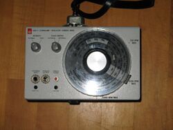
Harold Eugene Edgerton ("Doc" Edgerton) employed a flashing lamp to study machine parts in motion.[2] General Radio Corporation then went on to produce this device in the form of their "Strobotac", an early example of a commercially successful stroboscope.[3]
Edgerton later used very short flashes of light as a means of producing still photographs of fast-moving objects, such as bullets in flight.
Applications

Stroboscopes play an important role in the study of stresses on machinery in motion, and in many other forms of research. Bright stroboscopes are able to overpower ambient lighting and make stop-motion effects apparent without the need for dark ambient operating conditions.
They are also used as measuring instruments for determining cyclic speed. As a timing light they are used to set the ignition timing of internal combustion engines.
In medicine, stroboscopes are used to view the vocal cords for the diagnosis of conditions that have produced dysphonia (hoarseness). The patient hums or speaks into a microphone which in turn activates the stroboscope at either the same or a slightly different frequency. The light source and a camera are positioned by endoscopy.
Another application of the stroboscope can be seen on many gramophone turntables. The edge of the platter has marks at specific intervals so that when viewed under fluorescent lighting powered at mains frequency, provided the platter is rotating at the correct speed, the marks appear to be stationary. This will not work well under incandescent lighting, as incandescent bulbs don't significantly strobe. For this reason, some turntables have a neon bulb or LED next to the platter. The LED must be driven by a half wave rectifier from the mains transformer, or by an oscillator.
Flashing lamp strobes are also adapted for pop use, as a lighting effect for discotheques and night clubs where they give the impression of dancing in slow motion. The strobe rate of these devices is typically not very precise or very fast, because the entertainment application does not usually require a high degree of performance.
Fechner color
Rapid flashing of the stroboscopic light can give the illusion that white light is tinged with color, known as Fechner color. Within certain ranges, the apparent color can be controlled by the frequency of the flash. Effective stimuli frequencies go from 3 Hz upwards, with optimal frequencies of about 4–6 Hz. The colours are an illusion generated in the mind of the observer and not a real color. The Benham's top demonstrates the effect.[4][5][6][7]
See also
- Electrotachyscope
- Flip book
- Reciprocating motion
- Phenakistoscope
- Praxinoscope
- Strobe light
- Strobe tuner
- Tachometer
- Thaumatrope
- Zoetrope
References
- ↑ (in French) Les grands Centraux : Étienne Œhmichen (1884-1955] - Centrale-Histoire - École centrale Paris
- ↑ "Studies at MIT: 1926–1931 " Harold "Doc" Edgerton". 2009-11-28. http://edgerton-digital-collections.org/docs-life/studies-at-mit.
- ↑ "Trade catalogs from General Radio Corp". https://americanhistory.si.edu/collections/search/object/SILNMAHTL_16761.
- ↑ Benham, CE (1894). "The artificial spectrum top". https://scholar.google.com/scholar_lookup?hl=en&volume=51&publication_year=1894&pages=200&author=C+E+Benham&title=%E2%80%9CThe+artificial+spectrum+top%E2%80%9D.
- ↑ Pilz J, Marre E (1993). "Pattern-induced flicker colors. An ophthalmologic examination method (Article in German)". Ophthalmologe. 90 (2): 148–54. PMID 8490297.
- ↑ Schramme J (1992). "Changes in pattern induced flicker colors are mediated by the blue/yellow opponent process". Vision Research. 32 (11): 2129–34. doi:10.1016/0042-6989(92)90074-S. PMID 1304090.
- ↑ . Krantz, John H (2013). Encyclopedia of Color Science and Technology. New York: Springer Science+Business Media. doi:10.1007/978-3-642-27851-8_65-2. http://imbs.uci.edu/~kjameson/ECST/Krantz_FechnerColorsAndBehnamTop.pdf.
External links
- How the Germans Measured Milliseconds MECHANICALLY - Smarter Every Day 283
- Demonstration of Phenakistoscope and Stroboscope at North Carolina School of Science and Mathematics
 |
