Engineering:Voltage controller


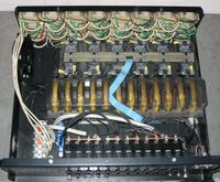
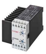
A voltage controller, also called an AC voltage controller or AC regulator is an electronic module based on either thyristors, triodes for alternating current, silicon-controlled rectifiers or insulated-gate bipolar transistors, which converts a fixed voltage, fixed frequency alternating current (AC) electrical input supply to obtain variable voltage in output delivered to a resistive load. This varied voltage output is used for dimming street lights, varying heating temperatures in homes or industry, speed control of fans and winding machines and many other applications, in a similar fashion to an autotransformer.[1][2] Voltage controller modules come under the purview of power electronics. Because they are low-maintenance and very efficient, voltage controllers have largely replaced such modules as magnetic amplifiers and saturable reactors in industrial use.[2]
Modes of operation
Electronic voltage controllers work in two different ways; either through "on-and-off control" or through "phase control".[3][4] [5]
On-and-off control
In an on-and-off controller, thyristors are used to switch on the circuits for a few cycles of voltage and off for certain cycles, thus altering the total RMS voltage value of the output and acting as a high speed AC switch. The rapid switching results in high frequency distortion artifacts which can cause a rise in temperature, and may lead to interference in nearby electronics.[2][4] Such designs are not practical except in low power applications.[6]

Phase angle control
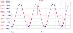
In phase angle control, thyristors are used to selectively pass only a part of each AC cycle through to the load. By controlling the phase angle or trigger angle, the output RMS voltage of the load can be varied. The thyristor is turned on for every half-cycle and switched off for each remaining half-cycle. The phase angle is the position at which the thyristor is switched on.
Applications

- Light dimming circuits
- Temperature control of electrical heating systems
- Speed control of motors
- AC magnet controls [7]
See also
- Dimmer
- Motor soft starter
- DC injection braking
- Space Vector Modulation
- Variable-speed air compressor
- Vector control (motor)
- Motor controller
- Adjustable-speed drive
- Electronic speed control
- Variable-frequency drive
- Thyristor drive
- DC motor starter section of Electric motor
References
- ↑ Andrzej M. Trzynadlowski (2010). Introduction to Modern Power Electronics. John Wiley & Sons. pp. 190–220.
- ↑ 2.0 2.1 2.2 Sachin S. Sharma (2008). Power Electronics. Firewall Media. p. 177. ISBN 9788131803509.
- ↑ Andrzej M. Trzynadlowski (2010). Introduction to Modern Power Electronics. John Wiley & Sons. p. 197].
- ↑ 4.0 4.1 Issa Batarseh, "Power Electronic Circuits" by John Wiley, 2003
- ↑ Trzynadlowski, Andrzej M (2010-03-15). Introduction to Modern Power Electronics. ISBN 9780470401033. https://books.google.com/books?id=o0IgIidEk8AC.
- ↑ Rashid, M. H. (2010). Power Electronics Handbook: Devices, Circuits, and Applications Handbook. Academic Press (3 ed.). Elsevier. pp. 488–490. ISBN 978-0123820365. https://books.google.com/books?id=eS1z95mzi28C&pg=PA488.
- ↑ "Fan drives for building facility and industrial systems". Kimo.de. 2012-02-28. http://www.kimo.de/index.php?file=anwend/luefter/luefter.html&lang=EN.
 |
