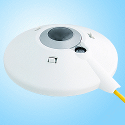
Physics:Pyrgeometer

A pyrgeometer is a device that measures near-surface infra-red (IR) radiation, approximately from 4.5 μm to 100 μm on the electromagnetic spectrum (thereby excluding solar radiation).
It measures the resistance/voltage changes in a material that is sensitive to the net energy transfer by radiation that occurs between itself and its surroundings (which can be either in or out). By also measuring its own temperature and making some assumptions about the nature of its surroundings it can infer a temperature of the local atmosphere with which it is exchanging radiation.
Since the mean free path of IR radiation in the atmosphere is ~25 meters, this device typically measures IR flux in the nearest 25 meter layer.
Pyrgeometer components

A pyrgeometer consists of the following major components:
- A thermopile sensor which is sensitive to radiation in a broad range from 200 nm to 100 μm
- A silicon dome or window with a solar blind filter coating. It has a transmittance between 4.5 μm and 50 μm that eliminates solar shortwave radiation.
- A temperature sensor to measure the body temperature of the instrument.
- A sun shield to minimize heating of the instrument due to solar radiation.

Measurement of long wave downward radiation
The atmosphere and the pyrgeometer (in effect its sensor surface) exchange long wave IR radiation. This results in a net radiation balance according to:
Where (in SI units):
- Enet = net radiation at sensor surface [W/m2]
- Ein = long-wave radiation received from the atmosphere [W/m2]
- Eout = long-wave radiation emitted by the sensor surface [W/m2]
The pyrgeometer's thermopile detects the net radiation balance between the incoming and outgoing long wave radiation flux and converts it to a voltage according to the equation below.
Where (in SI units):
- Enet =net radiation at sensor surface [W/m2]
- Uemf = thermopile output voltage [V]
- S = sensitivity/calibration factor of instrument [V/W/m2]
The value for S is determined during calibration of the instrument. The calibration is performed at the production factory with a reference instrument traceable to a regional calibration center.[1]
To derive the absolute downward long wave flux, the temperature of the pyrgeometer has to be taken into account. It is measured using a temperature sensor inside the instrument, near the cold junctions of the thermopile. The pyrgeometer is considered to approximate a black body. Due to this it emits long wave radiation according to:
Where (in SI units):
- Eout = long-wave radiation emitted by the earth surface [W/m2]
- σ = Stefan–Boltzmann constant [W/(m2·K4)]
- T = Absolute temperature of pyrgeometer detector [K]
From the calculations above the incoming long wave radiation can be derived. This is usually done by rearranging the equations above to yield the so-called pyrgeometer equation by Albrecht and Cox.
Where all the variables have the same meaning as before.
As a result, the detected voltage and instrument temperature yield the total global long wave downward radiation.
Usage
Pyrgeometers are frequently used in meteorology, climatology studies. The atmospheric long-wave downward radiation is of interest for research into long term climate changes.
The signals are generally detected using a data logging system, capable of taking high resolution samples in the millivolt range.
See also
References
 |
