Engineering:Amplidyne
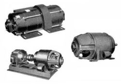
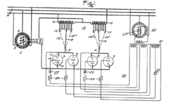
An amplidyne is an obsolete electromechanical amplifier invented prior to World War II by Ernst Alexanderson. It consists of an electric motor driving a DC generator. The signal to be amplified is applied to the generator's field winding, and its output voltage is an amplified copy of the field current. The amplidyne was used in industry in high power servo and control systems, to amplify low power control signals to control powerful electric motors, for example. It is now mostly obsolete.
How an amplidyne works
An amplidyne comprises an electric motor which turns a generator on the same shaft. Unlike an ordinary motor-generator, the purpose of an amplidyne is not to generate a steady voltage but to generate a voltage proportional to an input current, to amplify the input in applications where high output power is required. The motor provides the power, turning the generator at a constant speed, and the signal to be amplified is applied to the generator's field winding. The higher the current applied to the winding, the stronger the magnetic field and thus the higher the output voltage of the generator. So the output voltage of the generator is an amplified copy of the current waveform applied to the field winding. In a typical generator, the load brushes are positioned perpendicular to the magnetic field flux. To convert a generator to an amplidyne, what would normally be the load brushes are connected together and the output is taken from another set of brushes that are parallel with the field. The perpendicular brushes are now called the 'quadrature' brushes. This simple change can increase the gain by a factor of 10,000 or more.
The amplidyne's frequency response is limited to low frequencies, it cannot even handle audio frequencies, so its use is limited to amplifying low frequency control signals in industrial processes.
Historically, amplidynes were one of the first amplifiers to generate very high power (tens of kilowatts), allowing precise feedback control of heavy machinery. Vacuum tubes of reasonable size were unable to deliver enough power to control large motors, but vacuum tube circuits driving the input of an amplidyne could be used to boost small signals up to the power needed to drive large motors. Early (World War II era) gun tracking and radar systems used this approach.
Amplidynes are now obsolete technology, replaced by modern power semiconductor electronic devices such as MOSFETs and IGBTs which can produce output power in the kilowatt range.[1]
Use in gun mount control systems
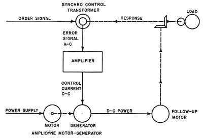
The amplidyne was first used in the US Navy in servo systems to control the electric motors rotating naval gun mounts, to aim the gun at a target. The system (diagram right) is a feedback control system in which a feedback signal from a sensor representing the current position of the gun is compared with the control signal which represents the desired position, and the difference is amplified by the amplidyne generator to turn the gun mount motor. The components are:
- a synchro control transformer;
- an amplifier;
- the amplidyne motor-generator, which is similar to a Ward Leonard control drive;
- and the follow-up DC motor which drives the load to be positioned.
Chapter 10 of the U.S. Navy manual Naval Ordnance and Gunnery, Volume 1 (1957) explains the operation of the amplidyne:[2]
- "The synchro control transformer receives the order signal which indicates electrically what the position of the load should be. The rotor of the synchro control transformer is turned by the response shaft, which is geared to the load and so indicates what the position of the load actually is. The synchro compares the actual load position with the ordered position; and, if the two do not agree, it generates an alternating-current signal which is transmitted to the amplifier. The angular difference between the two positions is called the error, and the signal to the amplifier is the error signal. The error signal indicates by its electrical characteristics the size and direction of the error. If no error exists, the system is said to be in correspondence and the error signal is zero."[2]
Specifically, the phase of the control transformer's output (in phase with the synchro power source, or opposite phase) provided the polarity of the error signal. A phase-sensitive demodulator, with the synchro AC power as its reference, created the DC error signal of the required polarity.
Applications
Amplidynes were initially used for electric elevators and to point naval guns, and antiaircraft artillery radar such as SCR-584 in 1942.[citation needed] Later used to control processes in steelworks.[citation needed]
Used to remotely operate the control rods in early nuclear submarine designs (S3G Triton).[citation needed]
Diesel-electric locomotive control systems. Early ALCO road-switcher locomotives used this technology.
Alternating current linear induction pump for secondary sodium in EBR-II.[4]
See also
- Brushed DC electric motor
- Harry Ward Leonard
- Magnetic amplifier
- Metadyne
- Motor-generator
References
- ↑ "Amplidyne - Working and Application | A Complete Guide" (in en-US). 2019-09-15. https://studyelectrical.com/2019/09/amplidyne-working-application.html.
- ↑ 2.0 2.1 Naval Ordnance and Gunnery, Volume 1, 1957, U.S. Navy Manual, Chapter 10.
- ↑ G. J. Thaler and M. L. Wilcox, Electric Machines, Wiley, New York, 1966, pp. 135-149.
- ↑ Experimental Breeder Reactor-II (EBR-II): An Integrated Experimental Fast Reactor Nuclear Power Station, Leonard J. Koch, American Nuclear Society (2008) ISBN 978-0-89448-042-1
External links
 |


