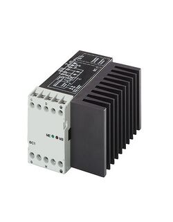
Engineering:Braking chopper
Braking choppers, sometimes also referred to as braking units, are used in the DC voltage intermediate circuits of frequency converters to control voltage when the load feeds energy back to the intermediate circuit. This arises, for example, when a magnetized motor is being rotated by an overhauling load and so functions as a generator feeding power to the DC voltage intermediate circuit.[1][2] They are an application of the chopper principle, using the on-off control of a switching device.
Operation
A braking chopper is an electrical switch that limits the DC bus voltage by switching the braking energy to a resistor where the braking energy is converted to heat. Braking choppers are automatically activated when the actual DC bus voltage exceeds a specified level depending on the nominal voltage of the variable-frequency drive
Benefits
- Simple electrical construction and well-known technology
- Low fundamental investment for chopper and resistor
- The chopper works even if AC supply is lost. Braking during main power loss may be required. E.g. in elevator or other safety related applications.
Drawbacks
- The braking energy is wasted if the heated air can not be used
- The braking chopper and resistors require additional space
- May require extra investments in the cooling and heat recovery system
- Braking choppers are typically dimensioned for a certain cycle, e.g. 100% power 1/10 minutes, long braking times require more accurate dimensioning of the braking chopper
- Increased risk of fire due to hot resistor and possible dust and chemical components in the ambient air space
- The increased DC bus voltage level during braking causes additional voltage stress on motor insulation
Applications
Braking choppers are inappropriate when:
- The braking cycle is needed only occasionally
- The amount of braking energy with respect to motoring energy is extremely small
- The ambient air includes substantial amounts of dust or other potentially combustible, explosive or metallic components
Braking choppers are appropriate when:
- The braking is continuous or regularly repeated
- The total amount of braking energy is high in respect to the motoring energy needed
- The instantaneous braking power is high, e.g. several hundred kW for several minutes
- Braking operation is needed during main power loss
Flux braking
Flux braking is another method, based on motor losses, for handling an overrunning load. When braking in the drive system is needed, the motor flux and thus also the magnetizing current component used in the motor are increased. The control of flux can be easily achieved through the direct torque control principle. With DTC the inverter is directly controlled to achieve the desired torque and flux for the motor. During flux braking the motor is under DTC control which guarantees that braking can be made according to the specified speed ramp. This is very different from the DC injection braking typically used in drives. In the DC injection method DC current is injected to the motor so that control of the motor flux is lost during braking. The flux braking method based on DTC enables the motor to shift quickly from braking to motoring power when requested.
In flux braking the increased current means increased losses inside the motor. The braking power is therefore also increased although the braking power delivered to the frequency converter is not increased. The increased current generates increased losses in motor resistances. The higher the resistance value the higher the braking energy dissipation inside the motor. Typically, in low power motors(below 5 kW) the resistance value of the motor is relatively large in respect to the nominal current of the motor. The higher the power or the voltage of the motor the less the resistance value of the motor in respect to motor current. In other words, flux braking is most effective in a low power motor.
See also
References
 |


