Engineering:Antenna types
This article gives a list of brief summaries of multiple different types of antennas used for radio receiving or transmitting systems. Antennas are typically grouped into categories based on their electrical operation; the classifications and sub-classifications below follow those used in most antenna engineering textbooks.[1][2][3][4](p4)
Categorizing antennas and organization of article sections
This section is an overview that lists the following sections and subsections in this article, in the order that those sections occur. Each group of antennas fit together based on some commonly used electrical operating principle: There is at least one aspect for which each group of antennas all work in the same way. The list below summarizes the parts of this article; the bold-face links in this subsection lead to the other article sections and subsections, each of which gives a summary description. In turn, the links within those summaries lead to relevant Wikipedia articles on antennas.
The listed antennas are clustered based on some shared principle(s) of electrical operation, so that antenna designs that use similar functional principles are listed close together. The order used is neither objective nor universal, but does conform to the organization used by many authors.[1][2][3][4](p4) Antennas can be classified in various ways, and various writers organize the different aspects of antennas with different priorities, depending on whether their text is most focused on specific frequency bands; or antenna size, construction, and placement feasibility; or explicating principles of radio theory and engineering that underlie, guide, and constrain antenna design. Further, different types of antennas are made with properties especially optimized for particular uses, and the electrical design of antennas serves as a way to group them:
- Most often, the greatest design constraint is the size (wavelength[lower-alpha 1]) of the radio waves the antenna is to intercept or emit.
- A competing second influence is optimization criteria for either receiving or for transmitting; the distinction has practical differences for the middle shortwaves and all longer wavelengths (the whole of the mediumwave and longwave bands).
- A competing third criterion is the number and bandwidth of the frequenc(y/ies) that a single antenna intercepts or emits.
- A fourth design goal is to make the antenna directional: To project radio waves toward or intercept radio waves from only one direction as exclusively as possible.
- Simple antennas
- There are three types of "simple antennas": dipoles, monopoles, and loops. The three simple antenna types are all typically (but not necessarily) used for transmission on frequencies where they self-resonate,[lower-alpha 2] however, resonance is often not critical for receiving, and typically merely a convenience rather than a necessity for transmission. "Simple" antennas are also used as building-blocks for the more complicated antenna types, such as composite antennas, which is analogous to assembling a combination of several simple optical lenses to make a single compound lens. Simple antennas are usually further subdivided into
- Linear antennas ("electric" antennas)
- "Straight-wire" or "straight-line" antennas are on rare occasions called "electric antennas", since they exclusively couple to the electric part of the electromagnetic radio waves that they emit and absorb.[lower-alpha 3]
- Dipole
- Two-armed antennas, like "rabbit ears". For resonance, each arm is slightly under a quarter-wave base to end, which makes the whole antenna nearly a half-wave end to end.
- Monopole
- Single-armed antennas, like a single "telescoping" antenna. At the lowest resonant frequency that arm is slightly under a quarter-wave long.
- Both dipoles and monopoles are often built large enough to be self-resonant; usually each arm is a quarter-wave long. However a few types of linear antennas are specifically made too small to resonate – short whip antennas, and unplanned random wire antennas, for example.
- Loop antennas ("magnetic" antennas)[lower-alpha 4]
- Loops are ring-like antennas made out of segments of wire or metal tubing bent into a circle or polygon – any regular or irregular two-dimensional figure that closes in on itself, with shapes having the largest enclosed area preferred. On rare occasions all loops are generically called "magnetic antennas",[lower-alpha 4] since they exclusively interact with the magnetic portion of the radio waves passing through them, as opposed to linear antennas (above) which are correspondingly "electric".
- Large loops
- "Large" loops are loop antennas whose perimeter is slightly over one full wavelength at their design frequency; they are naturally resonant on all frequencies that are whole number multiples of that design frequency.
- Halo antennas
- "Halos" are loops with a small gap cut in them, that naturally resonate at the frequency where their perimeter length is a half-wavelength.
- Small loops
- "Small" loop antennas are loops of wire or metal tubing designed for use as antennas at frequencies where their perimeter is smaller than a half-wave; they are not naturally resonant on any frequency they are used on, and must be resonated artificially, usually by attaching a capacitor across their feedpoint.
- Composite antennas
- Composite antennas are made by combining one or more simple antenna(s) either with other simple antenna(s) or with some kind of a metallic / conductive reflecting surface formed into a screen, or metallic curtain, or curved dish. Usually only one of the component antennas is resonant on the design frequency, and in that typical case, the feedline connects only to the resonant component.
- Broadbanded composite antennas
- Antennas can be made to be "broadband" or "wideband" in several different ways. Perhaps the most simple and common method of broadbanding is to combine two or more different antennas, connected at a single shared feedpoint, with each separate component readily accepting transmit power on a different collection of frequencies. The combined antenna then operates tolerably well on at least twice as many frequencies as a simple antenna.
- Array antennas
- Array antennas are made out of combinations of several simple antennas that function as a single antenna; most compact but highly directional / "high gain" / beam antennas are some type of an array antenna
- Aperture antennas
- Aperture antennas are made of an outer, surrounding reflective surface many wavelengths wide, whose shape concentrates waves striking the surface onto a small, inner, simple antenna; the inner antenna can be either resonant or non-resonant and of any type.
- The several subtypes of composites – broadbanded, array, and aperture antennas – are otherwise not especially closely related, and are often listed separately as distinct, unrelated types.
- Traveling wave antennas
- Traveling wave antennas are made from long wires, not far above ground and aligned in the direction from which signals are desired; also sometimes zig-zagging pairs (Template:Underoverset) of alternately diverging and converging wires are used, whose center-line aims in the desired receive direction. Traveling wave antennas are notable for being one of the few types of antennas that are normally not self resonant: Electrical waves induced by received radio waves travel through the antenna wire in the direction that the arriving RF signals are travelling. Only electrical waves traveling toward the feedpoint are collected; waves traveling away from the feedpoint are grounded through a terminating resistor at the end of the wire opposite the feedpoint. The resistive termination makes the antenna receive in only one direction; in their function, they achieve goals similar to an aperture antenna but traveling wave antennas are much simpler, so much easier to build. In order to make them even more directional, they are made several wavelengths long, hence unsteerable. Absorption in the terminating resistor makes them inefficient radiators, but still sometimes used for transmitting since they work on any frequency.
- "Other" antennas
- Some antennas don't comfortably fit in the categories used here, so this article's last section for real antennas is an "everything else" category for a few that aren't clearly one of the types of antennas listed here. For example, random wire antennas, and antennas that are laid down on the ground, instead of being raised high in the air, as normal antennas are.
- Isotropic antenna
- The last section is for a unique type of "fake" antenna, called an isotropic antenna or isotropic radiator. It is a convenient fiction used as a "worst possible case" that real antennas' directivity is compared to.
- Nearly isotropic
- Although no real antenna can be exactly isotropic, a few antennas are built to be as near to isotropic as possible, for use as emergency backup antennas and for testing performance of other antennas: Because the received and transmitted signal strength of an (almost) isotropic antenna is the same in (almost) every direction, their received and transmitted signal strength is (almost) the same regardless of whether or not they are carefully oriented.
Simple antennas
Dipoles and monopoles are called linear antennas (or straight wire antennas) since their radiating parts lie along a single straight line – ignoring convenience bends at the far ends, if any. On rare occasions they are called electric antennas since they engage with the electric part of RF radiation, in contrast to loops, which correspondingly are magnetic.
The term "linear" used to describe the typical shape of these antennas is not a strict criterion for the category: End-sections of a so-called "linear" antenna that are far from its center can be bent away from a straight line with hardly any noticeable electrical consequences; sag is common and comfortably tolerated in the nominally "straight" antennas; finally, in some varieties of "linear" dipoles, the two arms or "poles" can be bent into a "V" shape, even though each individually may be a mostly straight line.
Dipoles
-
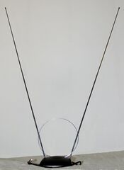 "Rabbit ears" dipole variant for VHF television reception
 -
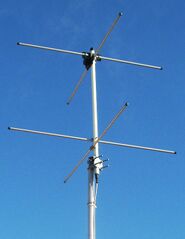 Two-element turnstile antenna for reception of weather satellite data (has circular polarization) at 137 MHz
 -
 Vertically mounted biconical (dipole) antenna
 -
![DIY "butterfly" antenna for TV signals, a flattened biconical[5]](/wiki/images/thumb/a/ae/Butterfly_television_antenna.jpg/173px-Butterfly_television_antenna.jpg) DIY "butterfly" antenna for TV signals, a flattened biconical[5]
DIY "butterfly" antenna for TV signals, a flattened biconical[5]


![DIY "butterfly" antenna for TV signals, a flattened biconical[5]](/wiki/File:Butterfly_television_antenna.jpg)
The dipole consists of two conductors, usually metal rods or wires, usually arranged symmetrically, end-to-end, with one side of the balanced feedline from the transmitter or receiver attached to each, and usually elevated as high as feasible above the ground.[3][lower-alpha 5] Some varieties of dipoles differ only in having off-center feedpoints or feedpoints at their ends, others vary the alignment or shape of the dipole arms.[7] Although dipoles are used alone as omnidirectional antennas, they are also a building block of many other more complicated directional antennas. All types of dipoles can be mounted either vertically or horizontally, and the chosen orientation determines their receive / transmit directions[lower-alpha 6] and wave polarity.
- Half-wave dipole
- The most common type of dipole consists of two resonant elements, each just under a quarter wavelength long, hence a total length of about a half-wave. This antenna radiates maximally in directions perpendicular to the antenna's axis, giving it a small directive gain of 2.15 dBi.[lower-alpha 7]
- Doublet
- "Doublet" is a name radio amateurs sometimes use for a dipole antenna that is used on a frequency below the antenna's lowest self-resonance. It is not necessary for an antenna to be resonant to transmit well, rather resonance is preferred to easily feed power to it; using a transmatch may make feeding power to an antenna on its non-resonant frequencies possible.[8][9][7] Some "doublets" are carefully sized to avoid resonance – and especially "antiresonances" – in order to make impedance matching for multiple frequencies less challenging. (The term is "doublet" is not strictly distinguished; many use it as a synonym for "dipole".[7])
- Folded dipole
- A typical folded dipole[lower-alpha 8] is two half-wave dipoles mounted parallel to each other, a few inches apart, with the far ends connected. Only one of the dipoles is fed, and the second dipole connects straight through the center where the first has the usual feedpoint. The two-wire version is often described as a "squashed loop antenna", since the total length of wire is one wavelength, and efficiency / feedpoint impedance of the folded dipole is very high: 4× that of a single dipole, analogous to the high efficiency of large loops. Any number of similar parallel wires may be added, with the efficiency rising as the square of the number of parallel wires; hence a three-wire folded dipole would a 9× greater impedance.{{citation needed|date=June 2025
- 'V' antenna
- When the two arms of a dipole are individually straight, but bent towards each other in a 'V' shape, at an angle noticeably less than 180°, the dipole is called a 'V' antenna. When the ends of the dipole's arms are about level with the branch point, it is called a flat 'V', or a horizontal 'V'; when its ends are much closer to the ground than their center branch-point, the antenna is called an inverted 'V' ('Λ'). The inverted 'V' is popular since it provides some of the good electrical performance of a dipole, but only requires one high mounting point, whereas an ordinary dipole requires at least two, often three. Due to a mixture of direct radiation and ground reflected radiation, the inverted-'V' tends to be mostly omnidirectional, but depending on the center angle, can slightly favor the direction along the midline between the two arms of the 'V'.[9][7][lower-alpha 9]
- Sloper
- A sloper or sloper dipole is a half-wave wire slanting down from a single elevated mounting point. It is usually fed at its center with the feedline cable itself slanting away at a perpendicular counter-slope from the sloping antenna wire, towards a small pole or a ground anchor near the base of the mast.[lower-alpha 10] The sloper's far end is attached to a short pole or fastened by an insulated cord to a ground anchor. It is popular because it requires only a single mast, and with a good ground system below it, has a nearly omnidirectional pattern.[2][7]
- Modern Windom antenna
- More formally called an off-center-fed dipole.[lower-alpha 11] The modern "Windom" is a dipole which is fed approximately one third of the distance from one of its ends, but otherwise erected like an ordinary dipole, including most dipole variations (such as inverted-'V' and sloper dipoles). The strategically chosen offset feed location has a fairly high impedance, but fortuitously shows roughly the same high impedance on most of its harmonics.[lower-alpha 12] The Windom antenna is popular because it has all of the advantages of an ordinary dipole, but functions well on almost twice as many shortwave frequencies as an identical sized center-fed dipole. The price for the extra working frequencies is the needed to match a feed impedance 5–7 times higher than the standard 50 Ohm transmitter impedance.[2][lower-alpha 13][lower-alpha 14]
- End-fed dipole
- A dipole can be fed from very near its end[lower-alpha 15] but at the ends, the impedances are exceedingly high – a few thousands of ohms, depending on the average height of the antenna and thickness of its wire. The end location has an inconveniently extreme impedance, but it is roughly the same high impedance for all the harmonics, and accommodation for any one harmonic will be near to right for all the other harmonics. The benefit of the extensive measures needed for matching to the high impedance[lower-alpha 16] is that the antenna can then function well on every harmonic (no exceptions, unlike a "Windom"), and hence can be used for transmitting on exactly twice as many frequencies as a same-size center-fed dipole (only odd harmonics feasible).[2][lower-alpha 17]
- Turnstile
- A turnstile antenna is made of two dipole antennas mounted at right angles, fed with a phase difference of 90°. This antenna is unusual in that it radiates in all directions (no nulls in the radiation or reception pattern), with horizontal polarization in directions coplanar with the elements, circular polarization normal to that plane, and elliptical polarization in other directions. Used for receiving signals from satellites, as circular polarization is used by most satellites for both transmit and receive, and since it can emit and receive signals in all directions, can operate from a simple, fixed mount, without needing to be aimed or steered towards the target satellite.
- Patch (microstrip)
- A patch antenna, or strip antenna, or microstrip, is a type of antenna with elements consisting of a shaped sheet of metal mounted over a second sheet that serves as the antenna's ground plane. The upper sheet is the radiating part of the antenna; it often has small, carefully sized and arranged holes cut into it that improve performance. Often, several parallel mounted strip antennas are combined into an array antenna. When used on airplanes the plane's skin serves as the ground plane, but is normally countersunk into the aircraft body so the overlying antenna strip can sit flush with the plane's metallic surface, to keep it aerodynamically smooth. The gap between the upper surface of the antenna and the plane's metal skin is then rimmed by a narrow, flight-worthy insulating material that seals the gap and securely holds the upper strip. Consequently, a surface-mounted strip antenna looks like a patch on the airplane body, hence the name. The performance of a patch antenna is similar to an ordinary dipole of the same length, with gain of 6–9 dBi. Small size for UHF and easy fabrication have made patch antennas popular in modern wireless devices, using parallel metal-plated sections on a printed circuit board's upper and lower surfaces for the radiating strip and its underlying ground plane.
- Biconical antenna
- A biconical is a dipole with cone-shaped arms, with the feedpoint where their tips meet; they are sometimes called "fat dipoles" or "double bowling pins". Biconicals show broader bandwidth than ordinary dipoles, up to three octaves above their base frequency. The monopole version is called a discone antenna.[lower-alpha 18]
- Bow-tie antenna
- A "bow-tie" antenna is a flattened version of a biconical antenna, with similar broad-band advantages. Also called butterfly antennas, they are dipoles with arms shaped like triangles or arrow-heads (▶◀ ᐅᐊ ⪥ ); the antenna feedpoint is where the tips of the triangles meet. The triangles can either be a metal sheet with solid metal centers (▶◀), or two wires with their far ends connected (ᐅᐊ) outlining the shape of a bow-tie, or with unconnected ends in an "X" shape (⪥).[7][5][lower-alpha 18]
Dipole and monopole design variability
Designs of linear antennas can be modified by using segments made of a bundled "cage" of wires instead of just a single wire, in order to simulate a single very "fat" wire. Another adaption is to bend otherwise straight segments near their ends, instead of only using completely straight wire, and exploiting the bent, folded, and zig-zagged dipole ends to fit in a tight space. Both of these adaptions to linear antenna designs are considered relevant, but minor distinctions between antennas.[2]
- Cage sections
- The elongated segments of dipole antenna are most often made of either thin, strong wire or hollow metal tubing. However they can also be made out of "cages" of wire: Several segments of fairly close-spaced, electrically parallel wire, simulate the electrical behavior of a much wider metal tube, but with lower weight and less trouble from wind loading; some of the performance improvements are lower loss, or "Ohmic" resistance, and wider bandwidth.[2] Although conical dipole (and monopole) segments are treated in this summary article as separate designs, wires bundled into "cage" segments are treated here as minor variations. The substitution of cage segment is sometimes limited to the radiating central portion of the dipole, with the outer segments left as thin wires. Any nominal antenna design using slim single-conductor wire can equally well be made substituting a "fat" cage for some or all of the antenna segments; the swapping in of "fat" segments provides a wider resonant bandwidth and a small improvement in radiation efficiency, and requires only slight (if any) shortening of the thicker segments.
- End folding
- Almost all of the radiation from a dipole comes roughly from the half of its total length closest to its center, around the usual feedpoint where the two arms meet; approximately the last third of each of the dipole arms only radiates a negligibly small portion of the outgoing signal, so for the purpose of emitting radio waves, the shape of each outer end is not critically important. This shape-indifference allows otherwise prohibitively long dipoles to have their far ends bent sideways, folded over,[lower-alpha 8] or zig-zagged, in order to shorten the antenna to fit inside an available space. This apparent mangling has very little effect on the antenna's radiation.[11][2][lower-alpha 19] For the most part, fold shapes are freely improvised by the person raising the antenna; various possible end folds are not listed in this article as a separate design, and should be considered a normal, electrically inconsequential convenience modification for every type of linear antenna.[11]
Monopoles
-
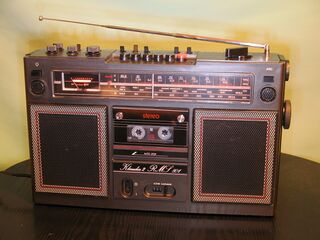 Quarter-wave whip antenna sized for 88–108 MHz, used for FM on a portable radio.
 -
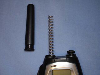 Rubber ducky antenna on 446 MHz UHF walkie-talkie with rubber cover removed.
 -
 VHF ground plane antenna.
 -
 Mast radiator antenna of medium wave radio station. The sideways radial arms on the top are a "capacitance hat".
 -
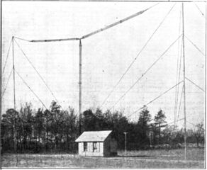 80 ft high 'T' antenna for 1.5 MHz, of a historic transatlantic amateur radio station. Note the vertical and horizontal "cage" sections.
 -
 Folded unipole antenna with a solid metal mast surrounded by six skirt wires, held away by insulated standoffs
 -
 Copper discone antenna for VHF or UHF


A monopole antenna is a half-dipole (see above); it consists of a single conductor such as a metal rod, usually mounted over electrically conductive ground, or an artificial conducting surface (called a ground plane, ground system, or a counterpoise).[3][12] They are sometimes classed together with dipoles (see above) in the broader category of linear antennas, or more plainly straight wire antennas, since their radiating section is normally a straight (linear) wire or section of metal tubing. Rarely, both dipoles and monopoles are called electric antennas,{{citation needed|date=June 2024} ctric field of a radio wave, to contrast them against all sizes of loops, which are correspondingly magnetic antennas.{{efn| name=magnetic_antenna_term_note| Loop antennas of any size are "magnetic antennas" in the generic sense; this meaning is different from, and not to be conflated with the confusingly similar common term "magnetic loop" used for small loop antennas ("small" means that the loop's total perimeter is shorter than half a wavelength). The separate term magnetic loop used to describe a small loop antenna is more specific than intended here for magnetic antenna,[citation needed]
One side of the feedline from the receiver or transmitter is connected to the radiating arm of the antenna, and the other side to ground or the artificial ground plane. The radio waves from the monopole reflected off the ground plane appear as if they came from a fictitious image antenna seemingly below the ground plane, with the monopole and its phantom image simulating an effectively complete dipole. Hence, the monopole antenna has a radiation pattern identical to the top half of the pattern of a similar dipole antenna, and a radiation resistance a bit less than half of a dipole. Since all of the equivalent dipole's radiation is concentrated in a half-space, the antenna has twice the gain (+3 dB) of a similar dipole, not counting any power lost in the ground plane.[2]
- Quarter-wave monopole
- A quarter-wave vertical is the most common monopole; it is a 1/ 4 wave tall vertical radiator; its size is the minimum length for a straight wire to self-resonate.[lower-alpha 20] A one-quarter wave monopole has a gain of 5.12 dBi when mounted over a good ground plane. A single monopole's radiation pattern is omnidirectional, so they are used for broad coverage of an area, and when mounted vertically, they have vertical polarization. Vertically polarized outgoing radiation is important for long-distance transmissions in the mediumwaves and lower: The ground waves that carry radio signals at frequencies below about 2 MHz must be vertically polarized to reduce signal absorption in the soil.[2] Large vertical monopole antennas are used for broadcasting in the lower half of the HF band, and all of the MF, LF, and VLF bands.
- Short whip
- Small whip monopoles are used as compact, but low-gain antennas on portable radios in the HF, VHF, and UHF bands. It is the type of antenna, typically shorter than a quarter-wave, often seen on mobile and portable radios such as FM "boom boxes". The "whip" consists of a flexible rod, often made of telescoping segments. In the HF band, the term "whip" is often used slightly differently to refer not only to any flexible antenna, but also to the terminal, self-supported, short segment at the top of a full-size vertical antenna. In the UHF and VHF bands a conveniently sized whip is long enough to self-resonate (a quarter wavelength or more); in that case, it is often just called by the generic name "monopole".{{citation needed|date=June 2024}
- "Rubber ducky"
- Rubber ducky is a commonly used 'joke name' for a plastic-covered spiral stub antenna; its more formal technical name is normal-mode helix. Most common antenna used on portable two-way radios and cordless phones due to its compactness. Consists of an electrically short wire helix that resembles a narrow, inch to half-inch long coiled wire spring, such as one might find in a retractable ballpoint pen. The helical shape adds both electrical length and inductance; the extra, compressed length lowers the excess capacitive reactance of the short radiator, and the inductance cancels at least part of that which remains, ideally making the helix resonant. Like all electrically short antennas it is nearly isotropic – has very low gain, if any.
- Not to be confused with the similar shaped, but much larger axial mode helix,[lower-alpha 21] nor loop antennas made from multiple stacked turns.[lower-alpha 22]
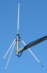
- Ground plane
- A ground plane antenna is a quarter-wave vertical whip antenna with several rods extending horizontally, or slanting down slightly, from base of the whip to form a portable ground plane that is fixed to the bottom end of the whip part of the antenna (hence the name). The ground plane stays in its position at the whip's base when the whip is moved, and is elevated along with the whip when the whole antenna is mounted at a high point, like the top of a mast. The rods that make up the elevated ground system can be any number from one to a half-dozen (usually three or four) arrayed in a mostly horizontal star-shaped pattern, similar to a downward-facing radiate crown. The radials at the monopole base form an elevated, artificial, electrical ground system that gives the antenna its name. The ground plane rods attach to the ground wire of the feedline, the other wire feeds the whip. Since the whip is mounted above ground, the horizontal rods form an elevated counterpoise just below the whip that reflects its radiation away from the soil below, and increases its gain.[2] Often used for elevated base station antennas for land mobile radio systems such as police, ambulance, and taxi dispatchers.
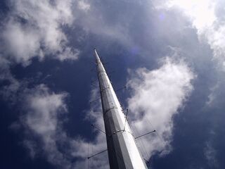
- Mast radiator
- A radio tower in which the tower structure itself serves as the antenna is called a mast radiator, or tower antenna, among other names. Common form of transmitting antenna for AM radio stations and other MF and LF transmitters. At its base the tower is often – but not necessarily – mounted on a ceramic insulator that isolates it from the ground.
- Folded monopole
- A folded monopole[lower-alpha 8] antenna is the monopole version of a folded dipole: It is an ordinary quarter-wave monopole with a second wire run parallel to the first, a few inches apart, with the top ends of the two wires connected. The second wire connects directly to the ground system instead of connecting to feedpoint as the first wire does. Adding the second wire raises the efficiency of the monopole by 4×, and correspondingly raises the feedpoint impedance, giving the added benefit of making impedance matching to standard coaxial cable somewhat easier. Similar to a folded dipole, one can add a third wire to get 9× the efficiency, and so on.[2]
- Although the name is similar to the folded unipole, the two antennas are electrically different: The folded monopole is a much simpler antenna.
- Discone antenna
- The discone is a monopole version of a biconical antenna. The name of the antenna describes its shape: A metal disk above a metal cone. The cone points upwards and is made of solid metal, wire mesh, or a skirt of about a dozen sloping wires that outline a cone. At the antenna's lowest operating frequency the cone measures near one quarter-wave long along the cone's sloping side, from tip to bottom rim. There is a smaller, flat metal disk mounted horizontally, slightly above the tip of the cone; sometimes the solid disc is replaced by a radiate crown of metal rods, similar to the base of a ground plane antenna. One of the feed wires connects to the tip of the cone, the other wire to the center of the disk. A discone is exceptionally wideband, offering a frequency range ratio of up to approximately 10:1 , over three octaves above the antenna's lowest frequency, but otherwise only functions just as well as other quarter-wave monopoles: It is omnidirectional, vertically polarized, equally efficient as a monopole, and has gain similar to a ground plane antenna.
- Folded unipole
- A folded unipole[lower-alpha 8] is an electrically modified mast antenna, usually grounded at its base, that has been augmented by one or several parallel wires called "skirt wires" that attach to the mast part-way up the antenna. The skirt wires can attach at any height between part-way up and the top of the mast. One or more of the skirt wires is fed with the signal, similar to a gamma match. The number and relative thickness of the mast and the skirt wires adjusts the feedpoint impedance.[lower-alpha 23] It is much more elaborate and not electrically the same as the similar-sounding folded monopole.
- Quarter-wave sloper
- A quarter-wave sloper or half-sloper is a quarter-wave wire that slants down from a single elevated mounting point, and is half the size of a sloper dipole – the monopole version of a sloper dipole (see above).[10] A quarter-wave sloper is fed at its top mounting point, with the low-hanging, far end attached by an insulated cord to a short pole or a ground anchor. Like the sloper dipole it is popular because it requires only a single tall mast. Also like a sloper dipole it has a nearly omnidirectional pattern when used with a good ground system. Because its strongest currents (near the top-end feedpoint) are high up, it tends to have a stronger signal toward the horizon (better low angle gain) than a monopole fed near its base.[2] It can be thought of as like a monopole version of an inverted 'V' dipole.
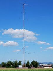
- 'T' antenna
- A 'T' antenna consists of a long horizontal wire crossing the gap between the tops of two towers, with a vertical wire attached to the center of the horizontal wire, hanging down from its center; the dangling vertical wire is the radiating part of the antenna. It is typically used for MF and the lower HF bands, where practical antennas are too short to be resonant. The wires outline the shape of the letter 'T', hence the name. The dangling wire may run directly into the back of a radio, but more often a 'T' antenna is fed by a cable attached near where the dangling wire comes to ground. Additionally, the antenna requires a low resistance ground system, normally centered directly below the bottom of the 'T'. The typical height of a 'T' antenna is shorter than the quarter wavelength required for resonance. A 'T' antenna is distinguished from the similar 'L' antenna by the place where the dangling, radiating wire attaches to the horizontal cross wire: For the 'T' antenna the dangling wire attaches to the exact center of the top horizontal wire. Current from the dangling wire feeds into the center of the horizontal section and flows away, left and right, in equal amounts; the balanced, opposing left-and-right currents do not radiate, but the unbalanced vertical current does radiate. Since for typically used frequencies, the vertical wire is much shorter than a quarter wavelength, the horizontal wire acts as a "capacitance hat" that increases the flow of current in the vertical radiator by giving it somewhere further to go, once it reaches the top. The increased current improves the efficiency and gain.[2][lower-alpha 24]
- Inverted 'L'
- An inverted 'L' is similar in construction to a 'T' antenna described above, but with the dangling vertical wire attached to one end of the horizontal wire instead of the center. The altered connection point gives the antenna the shape of the Greek letter 'Γ'. It can be thought of as an ordinary monopole that has been bent over somewhere in the middle, with its lower antenna segment vertical, as usual, but the "upper" part running horizontally – out sideways instead of up. Unlike the 'T' antenna, both the vertical and horizontal wires radiate, with their respective radiation being vertically and horizontally polarized, and their combined radiation diagonally polarized – usually at a steep angle. Although all parts of the antenna radiate, the strongest radiation comes from the vertical wire, so the horizontal wire serves both as a "capacitance hat" and as a weak radiator.[2][lower-alpha 25]
- Inverted 'F'
- An inverted 'F' is effectively a shunt-fed inverted-L, with the feed point attached to the horizontal wire, making the antenna shape like the letter 'F' tilted to the right by 90°, so it has the shape of the Hangul letter ㄲ, or the line-drawing character ╓. The unusual feedpoint with its adjustable location along the horizontal section gives the inverted 'F' the good feedpoint matching of a unipole, and the compact size of an inverted-L. The antenna is grounded at the base and fed at some intermediate point, and the position of that feed point determines the antenna impedance, so the feedpoint impedance can be matched to the feedline without needing a separate transmatch.
- Umbrella antenna
- An umbrella antenna is an elaborated and expanded version of a 'T' antenna; it is a very large wire transmitting antenna used on VLF bands for VLF time signals or long-range submarine communications. Umbrella antennas are enormous on human-scale but are paradoxically ultra-short antennas, relative to the even larger wavelengths they are built for. An umbrella antenna consists of a central radiating tower with multiple wires attached at the top as a "capacitance hat", that extend out radially from the mast and are insulated at their ends; the overhead configuration resembles an opened metal umbrella frame, hence the name. Since umbrella antennas are much smaller than a wavelength they have many troublesome properties: Extremely narrow bandwidth, low radiation resistance, and excessive capacitive feedpoint reactance. Like other ultra-short antennas they require both a large loading coil and a meticulously constructed low-resistance counterpoise system to cope with the exceedingly high negative reactance and minimal radiation resistance.
Loop antennas


Loop antennas consist of a loop (or coil) of wire. Loop antennas interact directly with the magnetic field of the radio wave, rather than its electric field as linear antennas do; for that reason they are on rare occasions called magnetic antennas, but that generic name is confusingly similar to the term magnetic loop normally used to describe small loops.[lower-alpha 4] Their exclusive interaction with the magnetic field makes them relatively insensitive to electrical spark noise within about 1/ 6 wavelength of the antenna.[3][13][2] There are essentially two broad categories of loop antennas: large loops (or full-wave loops) and small loops. The halo is the only loop antenna does not exclusively fit in either the large loop or small loop category.
Large loops
Full-wave loops have the highest radiation resistance, and hence the highest efficiency of all antennas: Their radiation resistances are a few hundreds of Ohms, whereas dipoles and monopoles are tens of Ohms, and small loops and short whip antennas are a few Ohms, or even fractions of an Ohm.[2]
- Large loops
- Large loops have a perimeter slightly larger than one full wavelength on their lowest resonant frequency. When they are one, two, or three wavelengths, or any whole-number multiple of a wavelength, they are naturally resonant and act somewhat similarly to the full-wave or multi-wave dipole. When it is necessary to distinguish them from small loops, they are called "full-wave" loops.[3][13][lower-alpha 26]
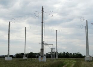
- Half-loop
- the upper half of a vertical full-wavelength loop antenna mounted on the ground. The full loop is cut at two opposite points along its perimeter, and the lower half is omitted; the upper half wired to an extensive ground system at each of the cut points, sticking up from the earth like a satchel handle. It is shaped like the Greek letter Π or an upside-down capital letter U, and is the loop antenna analog of a ground-mounted monopole antenna. Similar to how a vertical monopole uses its ground system to produce a "phantom" image of the rest of a dipole, the missing lower half of the half-loop is replaced by its image in the ground-plane. If shaped like a half of a square, a half-loop can operate either as a loop antenna or on its first harmonic as a dipole antenna whose ends have been bent over and grounded.[14][lower-alpha 27]
- Not to be confused with the visually similar but electrically different half-square antenna (see array antennas),[lower-alpha 28] nor the halo antenna.
Halo antennas
Halo antennas are loop antennas that uniquely sit in-between large and small loops; they are one half-wavelength in perimeter, with a small gap cut into the loop rim. For practical purposes, "halos" are only used on their lowest natural resonant frequency. Halos are intermediate in size and function between small and large loops, and are often described as a half-wavelength dipole that has been bent from a straight line into a round circle, but with its far ends left unconnected.[3][13][2][4](pp231–275)
Halos' radiation pattern is mostly in-plane and nearly omnidirectional, about the same as small loops' radiation. Halos' radiation efficiency is intermediate between the high efficiency of large loops and the generally poor efficiency of small loops. Halos are self-resonant like full-wave loops, but are almost never used on their higher harmonics. In some regards they represent the extreme upper size limit of small transmitting loops.[3][2][4](pp231–275)
Small loops
Small loop antennas' loop perimeters are smaller than a half-wavelength. They have very low radiation resistance – typically much smaller than the loss resistance of the wire they are made of, making them inefficient for transmitting. Their directionality and low radiation efficiency is drastically different from full-wave loops. If the loop needs to be resonant for transmitting or frequency-selective receiving, it must be electrically modified in some way to resonate it artificially – usually by attaching a shunt capacitor across the feedpoint.
Despite their drawbacks, small loops are widely used as receiving antennas, especially at frequencies below 10~20 MHz, where their inefficiency is not an issue and their small size makes them a useful solution to the excessive sizes even of quarter-wave antennas. The fact that they can be efficiently tuned to accept only a very narrow frequency range (similar to a preselector) helps alleviate much of the trouble caused by the pervasive static always encountered on the mediumwaves and lower shortwaves where small loops are most popular. Small loops are called "magnetic loops" (not to be confused with the more general category magnetic antenna, which includes small loops); they are also called "tuned loops" since small loops typically must be modified by adding capacitance to make them resonate on some frequency lower than any that they would "naturally" resonate on.
- Small receiving loops
- Small receiving loops are sized at 1/4~1/ 10 wave perimeters, sometimes with many turns of wire around the same supporting frame. Small loops are widely used as compact direction finding antennas, since as long as their perimeter is kept small enough, their "null" direction[lower-alpha 6] is exceptionally precise, and for hand-carried direction-finding equipment, their small size makes them more compact than dipole-based directional antennas.[3][13][2]
- Ferrite loop antennas
- Also called "loopsticks", they consist of a wire coiled around a cylindrical ferrite core (the "stick"). The ferrite increases the coil's inductance by hundreds to thousands of times, and likewise magnifies its effective signal-capturing area. The improvement makes them even more compact than (ordinary) small loops made without ferrite, and yet receive RF just as well (or better). Loopsticks' radiation pattern is identical to a dipole antenna, with a maximum in all directions perpendicular to the ferrite rod. These are used as the receiving antenna in most portable and desktop consumer AM radios made for the medium wave broadcast band, and for lower frequencies.[lower-alpha 29]
- Small transmitting loops
- Small transmitting loops are loop antennas whose perimeters are smaller than a half-wave, that have been specifically optimized for transmitting. Their much smaller size than dipole antennas (only ~10% as wide) sometimes makes them a viable choice when space is limited, despite their lower efficiency. Small transmitting loops are made larger in size than most small receiving loops, with perimeters near 1/3~1/4 wave,[lower-alpha 30] in order to improve on their generally poor efficiency. For that same reason, their parts are carefully joined by brazing or welding (not soldering) to reduce losses from contact resistance. Because of their larger size, small transmitting loops lack the sharp nulls[lower-alpha 6] of small receiving loops, so they are not as useful for direction finding, and also are more bulky (roughly double the size) so would not be as convenient as the more accurate small loops for hand-held use in radio searches.[2]
Highly accurate small loop null directions
The nulls[lower-alpha 6] in the radiation pattern of small receiving loops and ferrite core antennas are bi-directional, and are much sharper than the directions of maximum power of either loop or of linear antennas, and even most beam antennas; the null directionality of small loops is comparable to the maximal directionality of large dish antennas (aperture antennas, see below). For accurately locating a signal source, this makes the small receiving loop's null direction much more precise than the direction of the strongest signal, and the small loop / ferrite core type antennas are widely used for radio direction finding (RDF).
The null direction of small loops can also be exploited to exclude unwanted signals from an interfering station or noise source.[3][13][2]
Several construction techniques are used to ensure that small receiving loops' null directions are "sharp", including making the perimeter 1/ 10 wavelength, (or at most 1/4 wavelength). Small transmitting loops' perimeters are instead made as large as possible, up to 1/3 wave, or even 1/2, if feasible, in order to improve their generally poor efficiency; however, doing so blurs or erases small transmitting loops' directional nulls, unlike the precise nulls of smaller receiving loops.
Composite antennas
Composite antennas are made up of combinations of several simple antennas configured to function as a single antenna, analogous to how a compound optical lens combines multiple simple lenses. Likewise, for antennas that combine one or more simple antennas with a curved metal surface or flat reflecting screen, the metal dish or curtain functions for radio waves similar to a mirror in optical systems, hence those antennas are analogous to reflecting telescopes and Kleig lights.
Broadbanded composite antenna
Composite antennas are most often designed to bolster directivity beyond that of simple antennas. But a different performance-enhancement is to broaden an antenna's usable frequency range.[lower-alpha 31] Just by wiring together several simple antennas at a shared feedpoint, the resulting combined antenna can be made broadbanded or widebanded or multibanded – that is, made to operate well either on several distinct frequencies, or over a single, wider, contiguous span of frequencies.[lower-alpha 32]
- Fan dipole
- Also called a multi-dipole – a common broadband and / or wideband dipole variant that superficially resembles the bow-tie antenna, but is electrically different. It is a composite of pairs of dipole arms; both arms of one of the dipoles are equal-length, but each dipole pair is a different length from every other pair. The several dipole arms extend away ( ⚞⚟ ⪫⪪ ⫸⫷ ) from the common central connection point of the combined antenna.[lower-alpha 32]
- Fan monople
- A fan monopole, or multi-monopole is a half of a fan dipole: It combines several different-sized monopole antennas, all sharing the same feedpoint, with each sized to transmit well on a different band or sub-band. Like all monopoles, it requires a ground system to function. Its design for wideband or broadband behavior is essentially identical to the fan dipole.[lower-alpha 32]
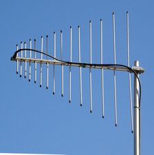
- Log-periodic dipole array
- Log-periodic dipole arrays are broadband because they are made from multiple dipoles share a common feedpoint, and so warrant mention in this section, but are fully outlined in the subsection on endfire arrays, below. Log periodic antennas are made with an aligned series of gradually shorter dipoles for directionality. As a consequence, the antenna hence transmits well (with varying gain) for the range of frequencies between the resonant frequency of its longest dipole in the back, through to the higher resonant frequency of its shortest dipole, in the front. The effective transmit frequencies have a broader range than the frequencies for which the dipole array is usefully directional.
Array antenna
Array antennas are composites of multiple simple antennas, either linear, or loops, or combinations of each. The multiple parallel-aligned simple antennas work together as a single compound antenna. The constituent simple antennas can be dipoles, monopoles, or loops, or mixed loops and dipoles. There are three or four types, called broadside arrays, endfire arrays, and parasitic arrays, among others.
Broadside arrays
-
 Sector antennas (white bars) on cell phone tower. Collinear arrays of dipoles stacked inside the tall white cases radiate a flat, fan-shaped beam.
 -
 VHF collinear array of folded dipoles
 -
 Four-bay collinear array of batwing television broadcasting antennas, Germany
 -
 TV antenna for the UHF 470–890 MHz band, with eight broadside arrayed bowtie dipoles backed by a reflective mesh curtain
 -
 Curtain array shortwave transmitting antenna, Austria. The front row of dipoles suspended between the towers is the transmitting "array", and the parallel row of dipoles behind them is the reflecting "curtain". The towers merely hold up the dipoles.


Broadside arrays consist of multiple, parallel or colinear, identical driven elements, usually dipoles. They can either be stacked along line - a vertical line of vertical elements or a horizontal line of horizontal elements – or they can be placed in a row of parallel elements – a vertical stack of horizontal antennas or a horizontal row of vertical antennas. The antennas are all fed in phase and collectively radiate a beam perpendicular to the plane containing the simple antennas, analogous to a firing line of musketeers, all simultaneously shooting in the same direction, perpendicularly out from the line of shooters.
- Vertical collinear
- A broadside array that consists of several dipoles, fed in phase, either with their axēs stacked atop each other, in a single vertical line, or more rarely lined up end-to-end horizontally. It is a high-gain omnidirectional antenna, meaning more of the power is radiated in horizontal directions and less wasted radiating up into the sky or down onto the ground. Gain of 8–10 dBi. Used as base station antennas for land mobile radio systems such as police, fire, ambulance, and taxi dispatchers, and sector antennas for cellular base stations.
- Curtain array
- A curtain array is any one of several designs for large, directional, long-distance, broadside transmitting array antennas used at HF by shortwave broadcasting stations. It consists of a vertical rectangular array of identical dipoles suspended in a parallel row in front of a flat reflector screen (the "curtain"). The screen or curtain consists of a second row of vertical parallel wires, all supported between two metal towers. It is aligned to efficiently radiate a horizontal beam of vertically polarized radio waves into the sky just barely above the horizon; once the signal reaches the ionosphere past the horizon the beam is refracted (or "bounced") off the F layer back towards Earth, to reach equally far beyond and over the horizon, perhaps to be reflected off the ground for another "hop". There are several designs for curtain arrays, among them Bruce arrays, Sterba curtains, bobtail curtains, and HRS antennas; the half-square antenna (below) is a minimal curtain array, with only two radiating elements and no reflecting screen.
- Reflective array
- Multiple dipoles in a two-dimensional broadside array mounted in front of a flat reflecting screen, usually called a "curtain". Used for radar and UHF television transmitting and receiving antennas.
- Half-square
- A broadside array made of two "upside down" vertical monopoles. Their dangling tips / bases correspond electrically to the tops of ordinary monopoles, and are not connected to the ground. The two top ends that each monopole hangs from electrically corresponds to the base of a normal monopole, and are the monopole's nominal feedpoints (the actual feedpoint for the combined system is often placed elsewhere). The attachment points at the tops are interconnected by a wire one half-wavelength long, which serves as both a counterpoise wire and a crossover phasing feedline. The verticals are the radiators and function as a minimal two-element curtain array, similar to a bobtail curtain. The structure is shaped like the Greek letter Π (not to be confused with the similar-looking half-loop antenna described above).[lower-alpha 28] Unlike a half-loop, neither monopole element has any DC connection to the ground beneath it (although there typically is considerable RF capacitive coupling, which can be exploited to shorten the verticals). The top-to-top half-wave connecting wire serves as a phasing line that keeps radiation from the two antennas in-phase; the line serves this function even though the feedpoint for the whole antenna system may be connected to some different part of the antenna. Since a quarter-wave monopole's current is highest nearest its feedpoint, the nominal top-feed puts the maximum current up high, at the top of each monopole; radiation is caused by (unbalanced) current, so hence the maximum radiation from a half-square antenna is generated from close to the top of the antenna. Because of being effectively top-fed, inverted monopoles tend to produce a better, somewhat stronger signal long-distance signals, with line-of-sight radiation in the clear and low to the horizon, as compared to radiation generated near the base of an ordinary bottom-fed monopole: Radiation from an ordinary monopole is mostly generated by the high current near the monopole's feedpoint at its base; that radiation is disadvantaged by its path to the distant horizon usually being obstructed by radio-reflecting electrical obstacles, such as metal fences, wiring built into houses, and metal-clad barns and warehouses.[14]
- Batwing
- Also called a superturnstile, is a specialized broadside array antenna used for VHF television broadcasting. It is a hybrid flattened biconical and turnstile antenna, that consists of perpendicular pairs of dipoles with radiators resembling bat wings. The batwing shape is a flattened biconic ("butterfly antenna") that gives wide bandwidth which whole-channel TV transmission needs. Stacking the batwings vertically on a mast concentrates more of the combined antennas' radiation in the horizontal direction, and with matched pairs at right angles, each pair fills-in the nulls of its counterpart, making their combined radiation pattern more nearly omnidirectional.[lower-alpha 18]
- Microstrip
- A small-sized microwave antenna printed on a circuit board (PCB). Because of the short wavelengths it handles, the small antenna can still be shaped to achieve large gains in compact space, as an array of patch antennas on a substrate fed by microstrip feedlines. Often the antennas printed on a PCB are composites of multiple different small antennas, each shaped to have complementary performance advantages supplementing the others'. Further, components' beamwidth and polarization can be made actively reconfigurable by switching and phasing circuitry printed on the same board. Ease of fabrication by modern PCB manufacturing techniques have made them popular in modern wireless devices.
Both broadside and endfire
-
 US Air Force PAVE PAWS phased array radar antenna for ballistic missile detection, Alaska. Each of the flat, round arrays is composed of 2677 individual crossed dipole antennas.
 -
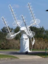
 Multi-directional composite loop antenna array installed at Penhale Point, near Kelsey Head, Cornwall.


This subsection could also be named "phased arrays", a type of composite directional antenna where the various component simple antennas are laid out a large fraction of a wavelength apart, with each antenna's feedline's phase individually shifted, so that the signal from a radio wave moving in some selected direction across the layout of the several simple antennas arrives simultaneously at the receiver, and hence constructively re-enforce; conversely, waves arriving from other directions will interfere destructively to either suppress or eliminate signals from the unwanted directions. The same phasing technique works in reverse, with signals transmitted from the several antennas combining to form a wave front departing mostly in one direction. Phase change can electrically steer the radiation receive and transmit direction without physically moving the antennas. Within limits, how narrowly a particular direction may be selected improves with a greater number of antennas, and / or with antennas spaced more widely apart.
- Phased array
- Is a high gain antenna used at UHF and microwave frequencies which is electronically steerable by phase adjustments, from being an endfire array to a broadside array, and every direction in between. It consists of multiple dipoles in a two-dimensional array, each fed through an electronic phase shifter, with the phase shifters controlled by a computer control system. The beam can be instantly pointed in any direction over a wide angle in front of the antenna. Used for military radar and jamming systems.
- Adcock antenna
- An Adcock antenna is a pair of side-by-side endfire arrays, hence it is also broadside. It is made of four parallel dipole (or monopole) antennas, all equal size and equidistant, vertically aligned at four corners of a square. All four dipoles are driven, but with opposing phases for adjacent dipole elements, and identical phases for elements at opposite corners. The combination of spacing and phasing of the dipole elements makes the combination of the arrayed elements moderately directional. Unlike phased arrays, Adcock antennas are typically physically rotated towards a given direction, rather than being steered by changing phase on the feedlines.
Endfire arrays
-
 Log periodic coplanar dipole array for 140–470 MHz

Endfire arrays have their driven elements fed out-of-phase, with the phase difference corresponding to the distance between them; they radiate within the plane that the constituent parallel antennas all lie in.[3][15][4](pp283–371)
Continuing with the musketeer analogy, an endfire array works similarly to a column of shooters, one behind the other; three, for example: One lying on the ground, the next kneeling behind the first, and the last standing at their backs, all aiming in the same direction they are lined up in, those in back firing over the heads of the musketeers in front of them. Each analogy musketeer fires his / her shot just as the bullets from the rearward musketeers' shots pass overhead, so that the combined volley of bullets are all bunched in an single aligned group, and all arrive at the target simultaneously.
- Log-periodic dipole array
- An endfire array of multiple dipole elements along a boom with gradually decreasing lengths, back to front, all connected to the transmission line with alternating polarity. It is a directional antenna with a wide bandwidth, which makes it ideal for use as a rooftop television antenna, although its gain is much less than a Yagi of comparable size. Sometimes called a "fishbone" antenna because of it looks like the ribs of a fish.[lower-alpha 33] For long wavelengths in the lower HF band the array may be made of ground-mounted monopoles instead of dipoles.
Parasitic arrays
-
 Yagi–Uda coplanar parasitic dipole array, with a folded dipole driven element, made for analog TV channels 2–4 and 47–68 MHz
 -
 Moxon antenna. Centers of the left and right segments and all of the middle boom are made of insulated tubing, keeping the long front and back segments electrically separate
 -
 Two-element quad antenna used by an amateur radio station with classic "box kite-frame" shape
 -
 Detail of a three loop "quad" made of large parallel-plane, round loops (so not actually quadrilateral)

.jpg)


Parasitic arrays are a specific type of endfire array that consist of multiple antennas, usually dipoles, with one driven element and the rest parasitic elements, which draw power from the radiated beam and then re‑radiate that signal power along the line of the antenna rods. It is parasitic arrays that are the closest RF analogs of compound optical lenses made from combinations of simple lenses. They can also be compared to a column of a team of especially skillful badminton players, with the server standing at or near the back, and each team-mate in front taking a swing at the shuttlecock as it passes by, to further it along with better aim.
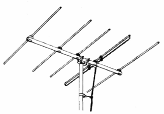
- Yagi–Uda
- Also called a "Yagi", is a parasitic array that is one of the most common directional antennas at UHF, VHF, and upper HF frequencies. A Yagi-Uda consists of multiple half-wave dipole elements aligned with their axēs parallel, in the same plane, with a single resonant-length driven element wired to the feedline, usually the next-to-last, next-to-longest element in the array.[lower-alpha 33] The multiple other elements are parasitic, which reflect and direct the radiated signal into a narrower beam, hence the name beam antenna.[lower-alpha 34] The simple antennas used to make a Yagi-Uda can either all be linear or bent linear antennas, or all loops (a quad antenna) or (rarely) a mixed combination of loops and straight-wire antennas.
- Yagi–Udas are used for rooftop television antennas, point-to-point communication links, and long distance shortwave communication using skywave ("skip") reflection from the ionosphere. They typically have gains between 10 and 20 dBi depending on the number of director elements used, but their bandwidths are very narrow.Cite error: Invalid
<ref>tag; refs with no name must have content
- Moxon antenna
- Also called a Moxon rectangle; it is a two dipole-element Yagi-Uda, hence a minimal parasitic array, whose dipole ends are bent towards each other and attached by an insulator into an overall rectangular shape. It is usually a driver-reflector dipole pair on the design frequency, but may additionally be used less optimally as a driver-director pair at another frequency. The ends of the separate dipoles are bent inward, towards each other, and connected by insulated cord or robust tubing to form a rectangular shape. Bending and connecting the ends makes the antenna more sturdy under wind load, and somewhat reduces the width, making the directional antenna easier to rotate than a full-width Yagi-Uda.[16]
- Quad
- Although "quad" can refer to a single quadrilateral-shaped loop, the term usually refers to two or more parallel-plane loops stacked as a parasitic array. Although very often the loops are indeed square-shaped, to minimize diameter and height, the individual loops can actually be non-quadrilateral shapes, despite the customary name. At first glance, square quads resemble a box kite frame. Only one of the loops in the quad is connected to the feedline, and that loop functions as the driver for the antenna and is the original source for the radiated signal. The other loops are parasitic elements that act as reflectors or directors, focusing the radiated waves in a narrower, single direction and thereby increasing the gain. Quad antennas are Yagi-Uda antennas made from loops instead of dipoles or monopoles, and are likewise used as a directional antennas on the HF bands for shortwave communication. They are sometimes preferred for longer wavelengths because (if square) they are half as wide as a Yagi built from dipoles and have slightly better directivity.[3][13][2]
Aperture antenna
-
 Corner reflector UHF TV antenna with "bowtie" dipole driven element at its center
 -
![University of Tasmania's parabolic radio telescope in Ceduna, SA[17]](/wiki/images/thumb/3/34/Ceduna_OTC%2C_South_Australia.jpg/349px-Ceduna_OTC%2C_South_Australia.jpg)
-
 Extremely high gain (~70 dBi) NASA Cassegrain dish antenna
 -
 Microwave horn antenna bandwidth 0.8–18 GHz
 -

-
 Dielectric lens antenna used in millimeter wave radio telescope.

![University of Tasmania's parabolic radio telescope in Ceduna, SA[17]](/wiki/File:Ceduna_OTC,_South_Australia.jpg)


An aperture antenna consists of a small dipole or loop feed antenna embedded inside a larger, three-dimensional surrounding structure that guides the radio waves from the feed antenna in a particular direction, and vice versa. The guiding structure is often dish-shaped or funnel-shaped, and quite large compared to a wavelength, with an opening, or aperture, to emit the radio waves in only one direction. Since the outer antenna structure is itself not resonant, it can be used for a wide range of frequencies, by replacing or retuning the inner feed antenna, which often is resonant.
- Corner reflector
- A directive antenna with moderate gain of about 8 dBi often used at UHF frequencies. Consists of a dipole mounted in front of two reflective metal screens joined at an angle, usually 90°. Used as a rooftop UHF television antenna and for point-to-point data links.
- Parabolic
- The most widely used high gain antenna at microwave frequencies and above. Consists of a dish-shaped metal parabolic reflector with a feed antenna at the focus. It can have some of the highest gains of any antenna type, up to 60 dBi, but the dish must be large compared to a wavelength. Used for radar antennas, point-to-point data links, satellite communication, and radio telescopes.
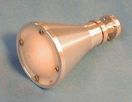
- Horn
- A horn antenna has a flaring metal horn attached to a waveguide. It is a simple antenna with moderate gain of 15 to 25 dBi, used for applications such as radar guns, radiometers, and as feed antennas for parabolic dishes.
- Slot
- Consists of a waveguide with one or more slots cut in it to emit the microwaves. Linear slot antennas emit narrow fan-shaped beams. Used as UHF broadcast antennas and marine radar antennas.
- Lens
- A lens antenna is made from a layer of dielectric, or a metal screen, or multiple waveguide structure of varying thickness, mounted in front of a feed antenna. The waveguide / screen / dialectric refracts the radio waves, focusing them on the feed antenna, similar to a focusing lens placed in front of a flashlight.
- Dielectric resonator
- The "resonator" part consists of small ball or puck-shaped piece of dielectric material, placed at the opening of a waveguide, where the material is excited by waves fed into the other end of the guide. If well-designed, the resonating material efficiently re-radiates the absorbed waves. Used at millimeter wave frequencies (c. 10~100 GHz).
Traveling wave antenna
-
 Animation showing a Beverage antenna .
 -
 Quadrant antenna, similar to rhombic, at an Austrian shortwave broadcast station. Radiates horizontal beam at 5–9 MHz, 100 kW
 -
 Array of four axial-mode helical antennas used for satellite tracking, France


Unlike the antennas discussed so-far, traveling-wave antennas are not resonant so they have inherently broad bandwidth.[3][4](pp549–602) They are typically wire antennas that are multiple wavelengths long, through which the voltage and current waves travel in a single pass, in one direction, as opposed to resonant antennas in which waves instead bounce back-and-forth to form standing waves.
In order to make traveling-wave antennas receive in a single direction, they are normally terminated by a resistor at one end,[lower-alpha 35] with the resistor's resistance matched to the antenna wire's characteristic impedance. Matching the impedance of the termination to the antenna wire maximizes the resistor's absorption of the waves traveling towards it along the antenna wire, hence almost no signals from unwanted directions are reflected backwards toward the feedpoint. Since the resistor absorbs the intercepted waves traveling towards its end of the antenna, the antenna feedpoint opposite the terminating resister only receives waves traveling in a direction away from the resistor and toward the feedpoint. When used for receiving the resistive termination removes more than half of the noise coming in from all directions, while preserving all signal power from the desired direction.
The longer a traveling wave antenna is (in wavelengths) the more narrow its receive direction becomes, approaching or exceeding the performance of compound beam antennas. The great lengths typical of traveling wave antennas makes them unsteerable, hence a fixed antenna must be erected for every desired direction. Individual traveling wave antennas are preferably about 1.5–2.5 waves from end-to-end, which requires a large space to place them. In the lower HF band, the difficulty of securing enough room to erect several long antennas for receiving from several directions makes traveling wave antennas infeasible for those without a large property.
If used for transmitting, the resistor makes traveling-wave antennas inefficient, since the resistor absorbs any radio wave after the wave has made a single pass through the antenna wire, as opposed to a resonant antenna in which radio waves cycle back-and-forth several times, giving the signal multiple opportunities to radate.[lower-alpha 36] However, because they are made non-resonant by the terminating resistor,[lower-alpha 35] traveling-wave antennas can easily be fed power regardless of frequency – unlike resonant antennas without transmatches, which are limited to frequencies very near their resonances. Because they have no practical restrictions on frequency, traveling-wave antennas may still be favored for transmitting if it is legally and electrically possible to raise the transmit power enough to compensate for the considerable amount of power wasted as heat in the terminating end resistor.
- Beverage
- Simplest unidirectional traveling-wave antenna. Consists of a straight wire one to several wavelengths long, suspended near the ground, connected to the receiver at one end and terminated at the other end by a resistor equal to its characteristic impedance (typically 400~800 Ω). Its radiation pattern has a main lobe at a shallow angle in the sky off the terminated end. It is used for reception of skywaves reflected off the ionosphere in long distance "skip" shortwave communication.
- Rhombic
- Consists of four equal wire sections shaped like a lozenge or rhombus ( ◊,〈〉). It is fed by a balanced feedline at one of the acute corners, and the two sides are connected to a resistor equal to the characteristic impedance of the antenna place at the opposite acute corner. The design makes for a good broadband shortwave receiving antenna with a somewhat directional horizontal main lobe, intercepting waves moving in the direction from the terminating resistor at one acute corner, towards the feedpoint at the other acute corner. The larger the rhombus, in wavelengths, the more directional the antenna is. Always a good receiving antenna, it can be used for two-way skywave communication when increasing transmit power enough to compensate for power dissipated in the terminating resistor is practical.
- Leaky wave
- Leaky wave antennas are used for microwave frequencies where microwave signals are normally passed through waveguides rather than solid wires. They are made by cutting slots, or "apertures", in a waveguide or coaxial cable, that allows the signal to radiate out along the length of the slot (hence "leaking" waves).
- Axial mode helix
- Consists of a wire in the shape of a helix mounted above or in front of a reflecting screen ( ⸠ꕊ ) whose total coiled length is on the order of at least one wavelength. Out of the open end of the helix, the antenna radiates a beam of circularly polarized waves, with a typical gain of 15 dBi. It is used at VHF and UHF frequencies where antenna sizes are feasible. Often used for satellite communication, which uses circular polarization because it is insensitive to the relative rotation on the beam axis.[lower-alpha 37]
- Not to be confused with a "rubber ducky" antenna (normal mode helix), which is much smaller.[lower-alpha 21]
Other antenna types
The following are some antenna types that don't comfortably fit into any of the types listed above.
Note that although it might well seem like a joke to describe antennas that are laid down on the ground (or even buried in it!) instead of put up high in the air, they actually do work, although with some limitations.
- Earth antennas, buried antennas, and ground antennas
- Earth antennas are made of wires actually buried under the soil, hence also called buried antennas; if laid onto the soil instead of buried in it, they are called ground antennas. Most amateur use is limited to non-directional mediumwave and longwave receiving antennas, but transmitting ground dipoles[lower-alpha 38] are used for military communication with submarines. In order to work, the wire must be near enough to the soil surface for the radio waves to penetrate and reach it; mediumwaves and longwaves are much better at penetrating soil, and although still rare, those are the bands buried antennas are most used on.[18][lower-alpha 39]
- Resistively loaded antennas
- One method for making a broadband antenna is to place a resistive element in the electrical path through the antenna, sometimes disguised by, and made somewhat more frequency-selective by embedding brass or tin inside an inductor. The extra resistance is used to dampen resonance and consequently reduce bothersome reactance found on most antennas at frequencies far from a resonance, and frequencies very near an antiresonance; the resistor's resonance dampening allows adequate operation on any frequency, but at the cost of wasting some transmit power in the resistor. Some examples are the terminated coaxial cage monopole (TC2M),[19] the tilted terminated folded dipole (T2FD), and the similar Robinson-Barnes antenna (essentially a T2FD with a third wire running parallel to the other two).[20][lower-alpha 35]

- Random wire antenna
- Moxon (1993) describes the random-wire antenna as an "odd bit of wire".[16] It is the typical informal antenna erected for listening to shortwave signals and for receiving AM broadcasts from distant stations.[lower-alpha 40] A random wire antenna consists of an unplanned / as-available length aerial, either strung outdoors between elevated supports, or indoors across a ceiling, running in an erratic zigzag pattern along walls or between supports.[lower-alpha 41] The near-end of the antenna wire is usually directly connected to the back of the radio.
Isotropic

An isotropic antenna (isotropic radiator) is not a real antenna: It is a hypothetical, completely directionless antenna that radiates equal signal power in all vertical, horizontal, and transverse directions. An old-fashioned incandescent light bulb is often used as an example of a nearly isotropic radiator (of heat and light). Paradoxically, every antenna of any type, whose electrical length is under ~1/10 wave in its longest dimension is approximately isotropic, but no real antenna can ever be exactly isotropic.
An antenna that is exactly isotropic is only a mathematical model, used as the base of comparison to calculate either the directivity or gain of real antennas. No real antenna can produce a perfectly isotropic radiation pattern, but the isotropic radiation pattern serves as a "worst possible case" reference for comparing the degree to which other antennas, regardless of type, can project some extra radiation in a preferred direction.
Nearly isotropic antennas
Real antennas that are nearly isotropic can be made by combining two or three small antennas, with each small element (electrical length shorter than ~1/10 wave) aligned differently from the others.
Nearly isotropic antennas are used as emergency antennas on satellites, since they work even if the satellite is tilted out of alignment with its communication station. They are also sometimes used for field strength meters, or as standard reference receive or transmit antennas for testing other antennas, since small mis-alignments are a non-issue: Their signal strength measures nearly the same for any orientation.
Omnidirectional is not isotropic
Isotropic antennas, which don't actually exist, should not be confused with omnidirectional antennas, which are real and fairly common.
An isotropic antenna radiates equal power in all three dimensions, while an omnidirectional antenna radiates equal power in all horizontal directions, but little or none vertically. An omnidirectional antenna's radiated power varies with elevation angle: Maximum in the horizontal, and diminishing as the altitude angle rises to align with the antenna's vertical axis. Several types of antennas – such as vertical, short whips or horizontal small magnetic loops – do not radiate at all in the exactly vertical direction, even despite wavelength increasing; compare that preservation of the null response in the vertical direction to the idealized isotropic antenna, which would radiate equally in every direction.
Notes
- ↑ 1.0 1.1
This article often refers to the wavelength of radio waves inside both antennas and their wiring, and for the cables they are connected to, but that length is physically slightly shorter measured length inside the antenna than the familiar wavelength for waves passing through the air (and in free space), determined by where λ inside the antenna is the shorter wavelength, and c inside the antenna is the slower speed of light. f is the radio frequency, which is the same both inside and outside. Problems understanding antennas arise if one fails to carefully track the different speeds of electricity inside the conducting materials of the antenna, all of which are smaller (slower) than the speed of light in free space, or at most equal to it: where is the (maximum) speed of light in a vacuum (or air), and c is the slower speed of light in the antenna. The ratio of the actual speed in the antenna to the free-space velocity is called the velocity factor closely related to the electrical length, and is the combination of three different causes, all of which are complications of the antenna wire's capacitance:
- The insulating material that surrounds the conductor retards the speed of light passing through it by changing the effective permittivity of the space around it. It can be caused by plastic insulation, protective plastic jackets on wires, or in some cases, metal-oxide pigments and fungicides in paint.
- Two other causes of effective shortening the antenna are the frustratingly complicated "end effects", which result in the conventional formulas for uniform wire capacitance per unit length to critically underestimate capacitance at the tips of the antenna. First, because of the more electrically open space near the tips of the antenna which cause a burst of excess capacitance per unit length ( C′ ) near the wire ends (see telegrapher's equations). Second, the stubby end(s) of the antenna beam or top of the antenna mast provide new surface for yet more capacitance. Aggravating the issue of these two causes of extra capacitance is that they both affect the part of the antenna where voltages are highest – incredibly high voltages, even for a few watts of transmit power.
- Yet another issue, although relatively minor in effect, is antenna-to-ground capacitance for parts of the antenna very close to the ground – something universal for the bases of vertical antennas, and fairly common for temporary antennas used on selected frequencies for transmitting straight up (NVIS) and bouncing backwards off the ionosphere, to get signals out of a confined location to a communications center no more than a few hundred miles distant. Other, much larger disturbances typically occur in low-hanging antennas, caused by radio waves reflected off the ground and back into the antenna raising counter-currents that conflict with current fed into the antenna.
- ↑ In a self-resonant antenna, the length of the conductive path through the antenna that waves of current and voltage pass through is sized so that a whole number of whole-, half-, or quarter-waves fit within it,[lower-alpha 1] depending on the antenna type. The waves fed into the antenna either bounce back and forth between the wire ends, or circulate around a closed loop. On resonant frequencies, the waves' overlapping sections add and subtract to make waveforms along the antenna segments; the composite waveform can shift position along the segment ("travel"), either quickly or slowly, or slow to a near stop ("stand"). At almost all frequencies, the waveform will be a traveling wave – it will shift along the antenna wire – but when the frequency is resonant, the wave's length (as a whole-, half-, or quarter-wave) is an exact fit to whole electrical length of the antenna. The waveform stops shifting and becomes a standing wave; which has the double benefits that the overlapping wave maximums (hence maximum radiation) stay in the location where they have the (presumably) best effect, and the nuisance reactance at the antenna's feedpoint vanishes.
- ↑ The term "linear" used to describe the typical shape of the antennas is not strict: End-sections of a so-called "linear" antenna that are far from its center can be bent away from a straight line with only slight or unnoticeable loss in performance.
- ↑ 4.0 4.1 4.2 Cite error: Invalid
<ref>tag; no text was provided for refs namedmagnetic_antenna_term_note - ↑ Dipole antennas are sometimes classed together with monopoles ("half-dipoles") (see below) in the broader category of linear antennas, or more plainly straight wire antennas. Both types' radiating parts are normally a straight (linear) pieces of aligned wires or aluminum tubing; rarely, they are called electric antennas, since they interact with the RF electric field, in contrast with loop antennas, which are correspondingly magnetic. The dipole (and half-dipole) is one of two basic antenna types upon which more elaborate compound antennas are based.[6]
- ↑ 6.0 6.1 6.2 6.3
An antenna "null" direction means that from that direction, the antenna is "deaf" on receive, and toward that direction is "quiet" on transmit. Usually a "null" means no signal at all, but some might informally refer to directions where an antenna's signal is weakest, but still present (rather than completely absent), as a "partial null", or similar. For any antenna, even though it may have a "sharp" null direction if mounted high-up and alone, reflections off the ground and / or nearby metal objects (such as other antennas) may blur a null direction into merely a "weak signal" direction.
- Linear antennas
- If they are straight (not bent) dipoles and monopoles always have a null off their ends, and depending on frequency, there might be nulls other directions as well.
- Large (full-wave) loops
- Large loops always have nulls within the plane of the loop on their lowest resonant frequency, but on higher harmonic frequencies they loose the in-plane null seen for their first harmonic; on their higher harmonics, large loops develop new nulls that emerge at various different inclination angles to the plane of the loop, with increasing numbers of different angles for higher-order harmonics.
- Halo antennas
- Even in the absence of ground reflections, halo antennas have no completely null direction, although their null-spoiling perpendicular radiation is still much weaker than their strongest radiation, in the plane of the loop.
- Small receiving loops
- Small receiving loop antennas always have nulls perpendicular to the plane of the small loop, the opposite the direction for large loops' nulls. A small loop's null begins to fade (shows a weak, non-zero signal) as frequency rises and the signal wavelength shrinks closer to twice the size of the small loop's perimeter. Conversely, as the frequency drops and the signal wavelength stretches past 10 times the small loop's perimeter, the plane-perpendicular null becomes exceedingly "sharp" (no signal at all, and focused in a very narrow direction).
- Small transmitting loops
- Not-so-small loops optimized for transmitting technically usually do not have completely null directions at their highest operating frequency, but do have very weak signals perpendicular to the loop plane. The plane-perpendicular direction with a very weak signal might be called a "partial null" or "incomplete null" or "faded null", as compared to a smaller loop's "sharp", complete nulls (no signal at all). The weak signal directions develop into completely null directions the lower the signal frequency falls below the frequency where the wavelength is twice the loop's perimeter; at a frequency low enough for the wavelength to be 10× the loop's perimeter or more, the loop will have a zero-signal "sharp" null.
- ↑ "2.15 dBi" means that in the direction of maximum radiation, signal strength is 100.215 = 1.64× the signal from a directionless "isotropic" antenna.
- ↑ 8.0 8.1 8.2 8.3 8.4 The use of fold in the phrase "folded ends" just means "bent"; it is not the same sense as fold in "folded dipole" or "folded unipole", where it approximately means "doubled-over", "overlapped", or "multiple".
- ↑ A horizontal or flat 'V' (ends level with the center branch point) is half of a shortened rhombic antenna (but usually not terminated) and becomes most directional at the 'V' branching angle around 40° – similar to a short rhombic antenna, but only roughly half as focused along the common axis that the arms point along, and bi-directional.[7]
- ↑ The elaborate arrangements for the feedline to slope perpendicular to the antenna is to prevent the feedline from picking up unbalanced current induced by the currents circulating through the center of the antenna.[2]
- ↑ Some writers prefer to call modern Windom antennas off-center-fed dipoles since the obsolete, original "Windom" type antenna was somewhat different. However, the common re‑use of the old name is well understood; belaboring the distinction comes off as tediously pedantic and largely irrelevant.
- ↑ A Windom antenna cannot be conveniently used on all of its harmonics; for example, the 3rd or 6th harmonics typically have prohibitively high feedpoint impedance. Details of what frequencies are and are not practical on any one Windom antenna will vary with slight differences in the feedpoint offset.
- ↑ A modern Windom antenna's feedpoint impedance is 250~350 Ohms, depending on wire thickness and fine adjustments in the feedpoint location that allow for different selections of usable harmonic frequencies. An ordinary dipole has a 67 Ohm feedpoint impedance – convenient for common 50 Ohm and 75 Ohm cable – but only for its odd-numbered harmonics. On frequencies near its even-numbered harmonics, an ordinary center-fed dipole's impedance is extremely high and varies erratically with small differences in frequency near the even-numbered resonance, and with slight misplacement of the feedpoint position. A Windom evades those problems for most harmonics by offsetting the feedpoint to a safer location, away from the troublesome center position, where the even-numbered harmonics have an antiresonance – a voltage peak and current node – with extreme impedance fluctuations close-by.
- ↑ Because a Windom antenna's feedpoint is placed near a high-voltage end of the antenna, its feedline tends to capacitively couple to the antenna, which drives unbalanced currents; these, in turn, cause radiation from the feedline if not blocked by two or three baluns. Modern designs, e.g. a Carolina Windom, exploit the radiating feedline current and only block it near where the cable reaches the ground, so that radiation from the vertical feedline partially fills-in the gaps that form in the horizontal dipole's radiation pattern on higher resonances.[2]
- ↑ The actual position of an "end fed" feedpoint only needs to be about 1/20th of the dipole length from the dipole's genuine electrical end, hence requiring only a vestigial counterpoise. Either on purpose or inadvertently, the outer shield of the feedline sometimes serves in disguise as the short, but necessary counterpoise.[2]
- ↑ Impedance matching for end fed antennas tends to use very high-ratio impedance transformers in combination with high-impedance feedline, which then connects to a remotely controlled (or automatic) antenna tuner, so the needed reduction of impedance down to the 50 ohm transmitter is a combination of multiple steps.[2]
- ↑ There are other benefits for how the antenna can be erected: The center third of any dipole's wire emits most of its radiation, and where that may be raised to is not limited by any need to reach it with the feedline; similarly, the extreme ends of any dipole do not radiate at all, so with the feedpoint attached to the end, that end may be sited at any convenient spot that is safe to put the end's extreme high voltage.[2]
- ↑ 18.0 18.1 18.2 Batwing antennas, biconical antennas, bow-tie antennas are electrically similar and have analogous advantages, such as being broadbanded.
- ↑ The only serious constraint on end folding is electrical safety: The dangerous high-voltage antenna tips (remarkably high, even for modestly low power transmission) must be out of harm's way, including anywhere a dangling wire might reach if blown by a strong wind.[2]
- ↑ A less often used, but better performing size is 5/ 8 wave. Because a 5/ 8 wave monopole is more than twice the height of the 1/ 4 wave, erecting one is more demanding. The payoff is that the greater length concentrates more signal (has better gain) in the horizontal direction, hence gives more power to long-distance transmission, and stronger signals for long-distance reception.
- ↑ 21.0 21.1 The total length of coiled wire in an axial mode helix is at least a whole wavelength, and made with just a few broad turns of wire, each of which is a large fraction of a wavelength in diameter. In contrast, a rubber ducky (normal mode helix) is small, made from a section of wire whose unwound length totals no more than a quarter wavelength; it is a tightly wound coil with many narrow turns of wire, each turn a tiny fraction of a wavelength in diameter.
- ↑ Also note that "rubber duckies" have no functional similarity to loop antennas: Although the antenna wire is indeed wound in a spiral with little loop-like turns, and although they do magnetically produce inductance, those turns are much too small to intercept or radiate any detectable signal magnetically, even when compared to the meager signal absorbed or emitted by the helically compressed monopole wire, functioning as a shortened electrical antenna.
- ↑
The folded unipole's mast and its surrounding skirt wires form an enormous vertical coaxial transmission line that is still small compared to the roughly quarter- to half-kilometer long mediumwaves it is typically used for. The central mast is the center conductor of the giant coax, and the skirt wires act as the giant coax's skimpy, conducting outer shield. The wires at the top of the skirt that connect the skirt and the upper mast short-circuit the coax, turning it into a giant loading stub. Since the stub is shorted and under a quarter-wave, it adds inductive reactance in parallel with the feedpoint.
- ↑ Since equal horizontal currents travel in opposite directions away from the center of the top wire, those currents balance and produce essentially no radiation. Usually the horizontal section is not long enough to supply sufficient capacitance, so the antenna feedpoint requires a loading coil to tune out any remaining reactance, and the tuned antenna will have narrow bandwidth. In the unusual case that its "capacitance hat" is wide enough to compensate for the missing length on the vertical wire, a 'T' antenna's performance can come close to a full-size monopole.
- ↑ If the length of the horizontal wire is sufficient to make the total length of wire about a quarter wavelength, the inverted-L's performance can come close to a full-size monopole.
- ↑ The popular "quad" antenna design is necessarily made from full-wave loops, usually two full-wave loops, so as long as the antenna is not merely "quadrilateral", no other distinction is needed.
- ↑ Being able to operate a half-loop as a dipole on its first harmonic mode depends on the position of the feed-point.
- ↑ 28.0 28.1 A half-loop antenna is electrically different from a half-square array antenna, despite the confusingly similar names and confusingly similar appearance (Π). The clearest distinction between them is that the ends of the half-square have no DC connection to the ground (although they are probably connected by capacitive coupling) and the ground system is optional; although helpful when the ends are close to the ground, a ground system may be omitted without loss when the ends of the half-square are very far above the ground. In contrast, each of the half-loop's ends must be shorted to a ground system, and the ground system(s) is(are) mandatory for it to function.
- ↑ The exceptions are car radios, which require an antenna mounted outside the metal car chassis, which blocks AM band and longer-wave reception.
- ↑ The upper size-limit for small transmitting loops is 1/2 wave, but impedance matching when approaching that upper limit becomes increasingly difficult. Loops between 1/2 wave and a full wave are certainly possible, but require inductive loading, and are more like a shortened, loaded full loop.
- ↑ There are different methods of broadbanding than combining several narrow-frequency antennas at their feedpoints: Another method is to put a terminating resistor onto a single antenna – similar to traveling wave antennas, but for a different reason. A resistor attached for broad-banding is used to dampen the antenna's wild swings in reactive impedance at non-resonant frequencies, which make resonant antennas difficult to use on non-resonant frequencies. The cost of adding a resistor is that it degrades antenna efficiency. This method of broadbanding is covered in the section on "Other" antenna types.
- ↑ 32.0 32.1 32.2 The multiple dipoles make the combined antenna wider-band than a simple two-arm dipole. The multiple wires spreading from the combined feedpoint are connected in equal-length opposing pairs, each pair different from the length of every other pair, which gives the fan dipole a wider range of resonances than any one dipole element. The basic idea is that the feed current will naturally flow mostly into whichever pair of wires offer the lowest impedance (best match) for the frequency being fed. If the several dipole pairs are nearly the same length, so that the bandwidths of their respective resonant frequencies overlap, the composite antenna will show a continuous matched bandwidth wider than any one dipole. If the dipole pairs' lengths are differ more broadly, so that their resonant frequency bandwidths do not overlap, the fan dipole will show multiple distinct resonant frequencies – with at least one resonance per pair.
- ↑ 33.0 33.1 Because of their similar "fishbone" shapes multi-element Yagi-Uda antennas and log-periodic antennas are often confused.
- ↑
A so-called "parasitic element" in a Yagi–Uda antenna that is slightly too long for resonance reflects the driven element's signal back towards it, similar to a mirror, and is called a "reflector". The reflector is usually the last and longest element in the array. Normally, there is only one of them.
- ↑ 35.0 35.1 35.2 Resistively terminated broadband antennas are sometimes arbitrarily included among traveling wave antennas, only because both involve a resistive termination. However, that is only appropriate if antennas are categorized by common construction, rather than by function. Traveling wave antennas are designed with resistive termination to eliminate waves traveling through the antenna in an undesired direction, giving them gain; some resistively terminated broadband antennas might happen to become directional, but that isn't necessary for them to become broadband.
- ↑ In resonant antennas, transmit power is spent by a combination of signal radiation and wire heating. Usually the power radiated from a resonant antenna far exceeds the power lost as heat.
- ↑ When a helical antenna has about 10 or more turns, with each turn near a full wavelength in circumference, then it is a "long helix" and its electrical operation is similar to a traveling-wave antenna. If it only has a few turns (or just one) and all the turns' totaled circumference is about one wavelength, or just a few wavelengths, then it is a "short helix" and operates electrically similar to some kind of large loop antenna.
- ↑ Ground dipoles are otherwise ordinary dipole antennas that are actually buried in the soil; in this instance "ground" really does literally mean earth or soil. They should not be conflated with ground plane monopole antennas. In the name "ground plane antenna", the word "ground" refers to the radio frequency electrical ground. It is a radial fan of rods connected to the antenna feed's ground, placed like an inverted radiate crown around the bottom end of a monopole, which is mounted high in the air. The fan of rods functions as a substitute for the monopole's ground plane.
- ↑ Despite seeming like a logical contradiction, a shallow-buried antenna can indeed receive radio waves, and for frequencies below the middle-HF (where receiving a strong signal is not a high priority, due to pervasive radio noise or "static") a little signal power absorbed in the soil is not too important. Another inducement is that "erection" by burial is a particularly practical way to lay-out an antenna in the lower MF and LF, where half-wave antennas can be more than a quarter-mile long (half-kilometer), and even an antenna put up as high as a two story building still remains only a tiny fraction of a wavelength above the ground, anyway. Amateurs experimenting in the 136 kHz band have even used the earth itself as a virtual antenna wire by connecting opposite ends of a feedline to two ground-rods placed far apart.[18]
- ↑ Random wire antennas are sometimes arbitrarily included as a sub-category of bent or folded[lower-alpha 8] monopole antennas, if their lengths are a quarter-wave or less, or folded end-fed dipoles if a half-wave or more, up to one or two wavelengths or less. When a random wire is laid out with at least one extended segment oriented in a straight line, one to several wavelengths long, a it operates roughly similar to a Beverage antenna, although since it presumably has no resistive termination, it will receive in two opposite directions, aligned with its longest segment, rather than being one-directional like a Beverage.
- ↑ The shape and length of a "random" wire is determined by the available space, locations and number of possible elevated attachment points, and how far the total available length of wire can reach. It is not laid out in a single straight line in a planned direction, and generally is not trimmed to any particular (resonant) length. A random wire antenna typically has a unique and complicated radiation pattern, with several lobes at varying angles to each wire segment, in different directions for each segment and for each frequency the segment is used on.
References
- ↑ 1.0 1.1 Bevelaqua, Peter J.. "Types of antennas". http://www.antenna-theory.com/antennas/main.php. — Peter Bevelaqua's private website.
- ↑ 2.00 2.01 2.02 2.03 2.04 2.05 2.06 2.07 2.08 2.09 2.10 2.11 2.12 2.13 2.14 2.15 2.16 2.17 2.18 2.19 2.20 2.21 2.22 2.23 2.24 2.25 2.26 2.27 2.28
Silver, H. Ward, ed (2011). ARRL Antenna Book for Radio Communications (22nd ed.). Newington, CT: American Radio Relay League. Chapter 5, Section 9.6, Section 11.6, Section 16.5, Section 20.6, Chapter 22. ISBN 978-0-87259-680-1. - ↑ 3.00 3.01 3.02 3.03 3.04 3.05 3.06 3.07 3.08 3.09 3.10 3.11 3.12
Aksoy, Serkan (2008). "Lecture Notes - v.1.3.4". Gebze, Turkey: Gebze Technical University. http://anibal.gyte.edu.tr/dosya/102/~saksoy/Lecture%20Notes/Lecture%20Notes%20-%20Antennas%20-%20Dr.%20Serkan%20Aksoy%20-%202008%20-%20v.1.3.4.pdf. - ↑ 4.0 4.1 4.2 4.3 4.4 4.5
Balanis, Constantine A. (2005). Antenna Theory: Analysis and Design. 1 (3rd ed.). John Wiley and Sons. ISBN 047166782X. https://books.google.com/books?id=jwjeAwAAQBAJ&pg=PA4. - ↑ 5.0 5.1 "Bow tie antenna". http://www.antenna-theory.com/antennas/wideband/bowtie.php.
- ↑ Bevelaqua, Peter J.. "Dipole antenna". http://www.antenna-theory.com/antennas/dipole.php.
- ↑ 7.0 7.1 7.2 7.3 7.4 7.5 7.6
Hall, Jerry, ed (1988). ARRL Antenna Book. Newington, CT: American Radio Relay League. p. 25⸗18 ff. ISBN 978-0-87259-206-3. - ↑ Maxwell, Walter M. (W2DU) (1990). Reflections: Transmission lines and antennas (1st ed.). Newington, CT: American Radio Relay League. ISBN 0-87259-299-5.
- ↑ 9.0 9.1 Moore, Cecil (W5DXP) (2014-01-09). "Old XYL's tales in amateur radio". http://www.w5dxp.com/OWT1.htm.
- ↑ 10.0 10.1 "Alpha Delta HF SWL sloper antennas". https://www.dxengineering.com/parts/alf-dx-swl#overview. — Example of a commercial website that uses half-wave sloper to describe a sloper dipole, and quarter-wave sloper to describe a sloper monopole.
- ↑ 11.0 11.1 Cebik, L.B. (W4RNL) (c. 2002). "Fold, bend, and mutilate – making a dipole fit the space available". http://webclass.org/k5ijb/antennas/Fold-Bend-and-Mutilate.htm.
- ↑ Bevelaqua, Peter J.. "Monopole Antenna". http://www.antenna-theory.com/antennas/monopole.php.
- ↑ 13.0 13.1 13.2 13.3 13.4 13.5
Bevelaqua, Peter J.. "Loop Antennas". http://www.antenna-theory.com/antennas/smallLoop.php. - ↑ 14.0 14.1 Severns, Rudy (N6LF) (1996). "Using the half-square antenna for low-band DXing". in Straw, R. Dean (N6BV); Roznoy, Rich (KA1OF). ARRL Antenna Compendium. 5. Newington, CT: American Radio Relay League. pp. 35–44. ISBN 0-87259-562-5.
- ↑ Bevelaqua, Peter J.. "Antenna arrays". http://www.antenna-theory.com/arrays/main.php.
- ↑ 16.0 16.1 Moxon, Les A. (G6XN) (1993). HF Antennas for All Locations (2nd ed.). Radio Society of Great Britain. ISBN 1-872309-15-1.
- ↑ "Radio astronomy". Ceduna Business & Tourism Association. http://www.ceduna.net/page.aspx?u=495#Radioastronomy.
- ↑ 18.0 18.1
Dodd, Peter B. (G3LDO) (October 1996). RSGB Antenna Experimenter's Guide. Ryan, Robert (illustrator) (2nd ed.). Potters Bar, UK: Radio Society of Great Britain. ISBN 978-187230936-1.
Republished Newington, CT: American Radio Relay League, ISBN 978-087259608-5 - ↑ Ehrenfried, Martin (G8JNJ). "The terminated coaxial cage monopole (TC2M)". http://www.tc2m.info/TC2M%20HF%20Vertical%20G8JNJ.pdf. "A new design of broadband HF vertical antenna."
- ↑ "Bushcomm HF Antennas". http://www.bushcomm.com.au.
 |  |
