Engineering:Tandem rolling mill
This article has multiple issues. Please help improve it or discuss these issues on the talk page. (Learn how and when to remove these template messages)
(Learn how and when to remove this template message)
|
,_entry_bridle,_2_stands,_exit_bridle_and_coiler_(tension_reel).jpg)
A tandem rolling mill is a rolling mill used to produce wire and sheet metal. It consists of two or more rolling stands placed close together. Each rolling stand contains a pair of heavy, motor-driven rollers—called work rolls—that squeeze the metal to reduce its thickness. As the metal passes from one stand to the next, the mill uses both the compressive force of the work rolls and the tension created between the stands to achieve a controlled, gradual reduction in thickness. The tandem rolling mill was first patented in England by Richard Ford in 1766.
Each stand of a tandem mill is set up for rolling using the mill-stand's spring curve[clarification needed] and the compressive curve of the metal so that both the rolling force and the exit thickness of each stand are determined. For mills rolling thinner strip, bridles may be added either at the entry and/or the exit to increase the strip tension near the adjacent stands, further increasing their reduction capability.
History
The first mention of a tandem rolling mill is Richard Ford's 1766 English patent for the hot rolling of wire.[1]
The development of transfer bar casting, also called thin slab casting [2] meant that slab roughing mills were no-longer required. Thin strip casting[3] with a thickness of 2 mm has bypassed the tandem hot mill; and further reduction in the casting thickness to produce strip steel the same as annealed cold rolled strip will bypass the tandem cold mill and the annealing process.
The need for tandem rolling mills, and rolling mills in general, is being[when?] reduced by the use of continuous casters.
Mill stand characteristics


The mill stand spring curve is obtained by pressing the work rolls together with increasing force. This causes the work rolls to bend, the screw-downs to compress and the mill housings to stretch. To reduce work roll bending, a much larger roll is positioned above the top work roll and another is placed below the bottom work roll. This arrangement is called a 4-high mill, as shown in sketch 1.
Calculating the screw-down position
The red line in graph 1 is the linear approximation F = Fd – M ⋅ (S – Sd) or conversely, the screw-down position
|
|
() |
where M is called the mill modulus and is the slope of the spring curve in the area of the datum point ( Sd, Fd). For most mills M is approximately 4 MN/mm. Larger values would require much thicker mill housings and screw-downs.
A datum is performed by lowering the screws below face until the measured force equals the required datum force Fd, at which point the screw-down position is set so that it equals the datum screw position Sd. At BlueScope Steel's No. 2 temper mill the datum point was 5 mm at a force of 7 MN.
Wood and Ivacheff analysed the information obtained when measuring the mill modulus by pressing the work rolls together until a typical rolling force was reached, and then they continued to measure the force and screw-down position as the rolls were lifted.[4] The shape of the plotted figures[clarification needed] (overlaid, looped, or a figure eight) was found to give good indication of the mill stand's condition.
The datum point is chosen so that the screw-down position S is never negative. This was necessary with the control computers of the 1960s, such as the GE/PAC 4020 installed at the then Australian Iron & Steel (now BlueScope) Port Kembla plate mill, which used an assembler language that did not like negative numbers.
Also, a datum point is used rather than trying to measure the point at which the force just becomes zero.[clarification needed]
The exact equation used to calculate the required screw-down setting for a required force is:[5]
|
|
() |
where: k is the value to best suit the measured values and Sa is an adapter which corrects for the thermal expansion of the mill housing and rolls as they warm up during rolling. It is set to zero after a work roll change, when the datum is performed with the new rolls at room temperature.
Using the measured values of F and S during the rolling of one piece of metal, allows the adaptor Sa to be calculated for use at the start of the next piece.
Roll force measurement

Load cells are used to measure the force exerted onto the work rolls by the product.
To obtain the true roll force acting on the work rolls the position of the load cells is important; are they with the filler plates under the bottom backup-roll bearings, or on top of the top backup-roll bearings. Both positions are shown in sketch 2.
Another thing that must be considered (if they are present) is the roll balance cylinders.
The roll balance cylinders act to separate the work rolls (no force between them) when the screw-downs are raised; that is, the force of the balance cylinders Fbal is just greater than the weight of the top roll set, (Wtbu + Wtwr).
The above roll weights Wtbu and Wtwr are only nominal values; the actual values will vary a little depending on how many times the rolls have been ground down between campaigns.
Since the roll weights are only nominal values, any residual error is slowly zeroed out whenever the roll balance is on and the screws are raised sufficiently.
Steel characteristics

A useful formula for the compression curve of steel is:[5]
|
|
() |
where
- K is the metal's hardness;
- H is the metal's initial thickness;
- h is the metal's exit thickness;
- k0 and k3 are grade dependent constants;
k0 moves the curve vertically, i.e. it sets the initial yield stress; k3 changes the slope, i.e. the metal's work hardening rate.
The initial steep section in graph 2 is elastic compression. The effective height of this is reduced by the entry and exit tensions when present, as in a tandem mill. Notice that the curve becomes steeper as the thickness approaches zero, i.e. it would take infinite force to make the steel infinitely thin.
The slope of the plastic region around the operating point is normally represented by the letter Q.
Mathematical modelling
For a rolling mill to operate, the work roll gap is set prior to the product entering the mill. Originally this setting was empirical; that is, set by the operators according to their experiences of that product's initial dimensions and the required finished thickness.
With a reversing mill, the profile of intermediate thicknesses was also empirical. To obtain greater consistency, attempts were made to characterize the rolling process. In 1948, Bland and Ford [6] were one of the first to publish such a mathematical model.
Essentially such mathematical models represent the mill (its spring curve) and the compressive behavior of the product to calculate the mill's "setup".
Mill setup calculation
The term "setup" is used for the calculation of the actuator settings required by each mill stand to roll the product. These settings include the initial screw-down position, the main drive speed, and the entry and exit tension references where applicable.
This setup calculation is normally performed either in a lower-level computer or a PLC that controls a rolling mill stand(s).

A graphical representation of a mill model can be obtained by plotting the mill stand spring curve and the compression curve for the strip against the same distance axes; then the intersection point gives the solution of expected rolling force F, and final Strip Thickness h, and also the required initial screw-down position So. See graph 3.
In its simplest form
|
|
() |
This equation is known as the BISRA equation. It is also known as the gaugemeter equation because measurements of S and F can be used to calculate the exit thickness as measured by an instrument called a thickness gauge.
If the work rolls are initially pressed together by the screw-downs, then there will be a force Fo acting between the top and bottom work rolls before the strip is present. In this situation, the Mill is said to be set "below face", as shown in graph 3. This is often the case with thin strip.
However, if there is an actual gap before the metal enters the mill, then Fo will be zero, and (from equation 1) So must be greater than Sd + Fd / M
The calculation is repeated for the following stands with the exit thickness h of the one stand becoming the entry thickness H of the next stand. Note that the compression curve has a greater or lesser elastic region depending on the entry and exit tension stresses of that next stand.
Interstand tensions

One could say the steel is compressed by the force of the work rolls, equivalent to forging; however, if there are tensions present, then it could be said that the steel is stretched by the tension pulling it through the rotating work rolls, as in extruding through a die. See sketch 3.

The tensions reduce the effective elasticity of the product by an amount equal to the induced tension strain. This tension effect is represented in graphs 2 and 3 by drawing the steel compression curve with the elastic region reduced accordingly.
The relationship of the rolling force to the entry and exit strip tensions is important in determining the finished strip flatness.[7] Too much force produces strip with edge wave (often called "pressure wave"). Too much tension, that is too little force, can cause center buckle (depending on the crown of the rolls).
The tension stress is 30% to 50% of the yield stress for cold mills and often higher in hot mills (which can result in heavy necking and even strip breaks).
In sketch 4, observe that the force is offset from the work roll centers because the strip is thicker at the entry than at the exit; this is one component of the torque that the main drives must supply. The other component is the difference in the tension forces. If the exit tension force is much greater than the entry tension force, then the tension torque may be larger than the torque due to the rolling-force and the main drives will generate power.
The neutral point, or no-slip point[8] is the point within the roll bite where the work rolls and the strip are doing the same speed.
The position of the neutral point is influenced by the entry and exit tensions.
Shudder occurs when the neutral point is at an edge of the roll bite; that is the work rolls are alternately grabbing the strip and letting it slip.
Forward slip (1+f) is the ratio of the exit strip speed to the work rolls peripheral speed. Backward slip (1−b) is the ratio of the entry strip speed to the work rolls peripheral speed.
Roll wear
As the strip slides through the work rolls it polishes them and the strip. This changes the friction coefficient of the strip-to-roll surface. So, to predict the forces and the power required to drive the work rolls, the mill modelling estimates this roll wear based on the length of strip rolled.
To reduce the friction in the roll bite, a warm oil-water emulsion is sprayed at the entry side of the roll bite in cold rolling mills.

The work rolls of all the stands in a tandem mill are normally changed at the same time. The new work rolls will have been ground to restore their desired crown and roughness. When this is done, the roll wear is reset to zero in the modelling.
The heat generated in the roll bite of a cold mill warms both the strip and the rolls. Since the cold mill rolls have no coolant applied, just a small amount of warm oil-water emulsion, the work rolls in a cold mill become hotter than those in a hot mill, where copious amounts of cold water are sprayed at the exit side of the roll bite.
Back-up roll bearings speed effect
The back-up roll bearings are usually white-metal bearings which rely on a film of oil between the shaft and the white-metal to reduce the friction; as seen in sketch 5.
As the speed increases more oil is dragged into the active region of the bearing and this increases the thickness of the oil film in this region. This pushes the top work roll down and the bottom work roll up, which reduces the roll gap in the same manner as running the screws down. To compensate for this, most screw-down control loops include a feed-forward parameter derived from either; an equation of rolling speed, or a value extracted from a lookup table using linear interpolation.
To ensure an oil film exists even at zero speed; pumps are often used to force oil through very tiny holes into the bearing's active region; this is referred to as hydrostatics.


In Chart 1, the scale for the screw-downs position (mauve trace) was 0.2mm per division; this was too coarse. Consequently Chart 2 was created from a similar coil, but with a screw-down position scale of 0.06mm per division; that is, from 5.8mm to 6.4mm.
In the chart recordings, notice that the force (light green trace) has been held constant by the automatic control, which has raised the screw-downs (mauve trace) as the speed (red trace) has increased. This increase in screw position is a measure of the white metal bearing speed effect.

For a more accurate measurement, the force of each mill stand is measured as it is run through its speed range without strip present.
The values measured from Chart 2 were plotted in an Excel spreadsheet. The equation that was used to match the measured points was 680×POWER((speed/1200),0.225)-285.
Note that the use of oil hydrostatics can hold the oil film nearly constant up to about 20% of full speed; hence no screw-down movement would be required in that low speed range (this is shown as the red line in the graph of the measured points).
Now recall the gaugemeter equation in its simplest form:
This equation is modified to include the backup roll bearing speed effect Sv especially when rolling product which has a thickness similar to the speed effect (~400 μm at some temper mills). Thus,
|
|
() |
Discontinuity in the stress verses strain of annealed steel

The discontinuity in the stress/strain of annealed steel[9] makes it impossible to create round tinned steel-cans. Wherever the steel bends first is where most of the bending will occur, rather than uniformly.
The discontinuity is shown within the red circle in graph 4. It is the reason the strip is given a light reduction (~1.3%) normally referred to as an elongation or extension.
Since it is referred to as an elongation and not a reduction, this strip is said to have been reduced only once (at the cold mill prior to annealing); hence the term single reduced (SR).[10]
After the elongation, the discontinuity is no longer present.
Alternatively; after annealing, the steel strip can be reduced a second time (by up to 30%) to make it both thinner and work hardened.[11] When this is done, the strip is said to have been reduced twice; that is, doubled reduced (DR).
Grade adaption
While a tandem mill is rolling, the "setup" computer collects the following information:
- motor currents, voltages and speeds
- strip tensions
- rolling forces
- roll gaps (screw-down positions)
- X-ray gauge(s) readings.
It also has available the coil's schedule information:
- entry thickness and width
- required exit thickness
- grade of steel
The actual rolling forces are compared with the forces predicted by the mill model given the information obtained. Any differences adjust the calculated forces by trimming the force adaptors, Fa . Thus equation 5 becomes
Recall that equation 3 gave the compressive strength of steel at BlueScope steel's 5 stand cold mill
The average value of the force adaptors trimmed the value of k0 for the actual grade being rolled. Also the slope of the force adaptors corrected the work hardening rate, k3 for the same grade of steel. The value of k3 for super-strapping was approximately twice that for normal tin-plate. This made switching between grades from coil-to-coil much smoother.
Threading
A few difficulties arise when threading any tandem cold mill.

Stand 1 closed gap Stand 2 open gap
One way to minimize these problems is to use "open-gap" threading.
With open-gap threading, the next stand to be threaded has a roll gap greater than the thickness of the strip. Once threaded, the top work roll is lowered onto the strip and then the strip moves on. Open-gap threading ensures that the head-end does not mark the work rolls as it enters the roll-gap. And having the strip stopped as the screw-downs are lowered avoids skidding as the work roll just touch the strip.
For "closed-gap" threading of a tandem mill, it is important that the head-end of the strip remains flat so that it enters the next stand easily. Immediately the strip enters a stand, there is no tension on either side of it; this means that the force would be greater than during rolling, so the roll gap (screw-downs) initially needs to be increased a little with respect to that required during rolling in order to prevent excessive edge-wave.
The closed-gap screw-down setting is calculated using the mill model for thread speed and with no tensions.
Another issue with closed-gap threading is the speed of the stand being threaded. It needs to be faster than the proceeding stand, so that the strip doesn't build up between the stands; but not so fast that it pulls the strip taught too quickly and breaks the strip.
In all cases, the strip's head-end will remain thicker because of the lack of tensions as it is threaded; consequently there will be a sizeable amount of head-end off-gauge strip that must be scrapped later.[12]
Notice in the gif simulation, that the head-end speed remained constant when moving. This was the practice at BlueScope Steel's 5 stand cold mill.
Control issues
The control of a tandem rolling mill is multi-layered.
Two examples are shown for BlueScope Steel's No.2 temper mill with the exit stand configured for strip shape (flatness).


At the lowest level is the current/voltage control of the DC electrical drive motors.
At this level the bridles and reels are in open-loop tension mode; this means they run with a voltage which is related to the strip speed and a current controlled according to the tension required in the nearby strip. The tension reel has a motoring current to pull the strip taught, and the payoff reel generates to pull back against the strip. To keep these tensions constant during acceleration/deceleration of the mill, an additional current must be applied to the reels and bridles to produce the extra torque required to accelerate/decelerate them, especially when there is a large part of a coil on a reel. This is referred to as “inertia compensation”.
Above the direct motor controls, is the last stand's force control which sets the strip flatness. The rolls heat up slowly while processing a coil, and this would close the roll gap and increase the rolling force; however, to prevent this increase, the force control raises the screw-downs occasionally, as required.
Also at this level is the inter-stand tension control. It can act into either of the adjacent stands, but as in the diagrams shown, it acted into both stands in the proportions shown.
The thickness/elongation controls and speed profile sit above all of the other control loops. The speed profile is determined in the mathematic modelling according to the desired reduction. It is multiplied by the master ramp's speed as set by the operator using his/her inputs, which are: thread (go to thread speed); run (accelerate to top speed); hold (stop acceleration/deceleration); stop (steady deceleration to zero speed); and emergency stop (uses maximum deceleration possible).
Back-up roll eccentricity
With hot rolled slabs and plates, the thickness varies mainly due to the changes in the temperature along the length. The colder sections are a result of the supports in the re-heat furnace.
When cold rolling, virtually all of the strip thickness variation is the result of the eccentricity and out-of-roundness of the back-up rolls from about stand three of the hot strip mill through to the finished product.

The back-up roll eccentricity can be up to 100 μm in magnitude per stack. The eccentricity can be measured off-line by plotting the force variation against time with the mill on creep, no strip present, and the mill stand below face.
A modified fourier analysis was employed by the five stand cold mill at Bluescope Steel, Port Kembla from 1986 until that cold mill ceased production in 2009. Within each coil, the exit thickness deviation times 10 for every meter of strip was stored in a file. This file was analyzed separately for each frequency/wavelength from 5m to 60m in steps of 0.1m. To improve the accuracy, care was taken to use a full multiple of each wavelength (100*). The calculate amplitudes were plotted against the wavelength, so that the spikes could be compared to the expected wavelengths created by the backup rolls of each stand.
If a mill stand is fitted with hydraulic pistons in series with, or instead of the electrically driven mechanical screws, then it is possible to eliminate the effect of that stands back-up roll eccentricity.[13][14] While rolling, the eccentricity of each back-up roll is determined by sampling the roll force and assigning it to the corresponding portion of each back-up roll's rotational position. These recordings are then used to operate the hydraulic piston so as to neutralize the eccentricities.
Sensitivities and their uses

In a tandem rolling mill, the gearing of the screw-downs is normally large enough that the work rolls can be moved during rolling. With such a ratio the worm gear is said to be self-locking; that is, the rolling force is unable to push through the worm drive and rotate the electrical drive motor. This means that no brake is attached to the electrical motor.
If during rolling, it is necessary to move the screw-downs to correct either the rolling force or the exit strip thickness, then consider the triangle, shown circled in the graph 5 and enlarged in sketch 6, created when the screw-downs are moved down from the purple line to the green line.
The strip becomes thinner and the rolling force increases.

ΔS = Δh + a with ΔH = 0, but the slope Q = ΔF / Δh, and the slope M = ΔF / a
Therefore, ΔS = ΔF / Q + ΔF / M
Which gives
|
|
() |
This term is used to ensure that the control of the rolling force using the screws is independent of the metal being rolled.
Using ΔF = Q ⋅ Δh gives
|
|
() |
This factor is used to guarantee that the control of the exit thickness by the screws is independent of the metal being rolled.
The process sensitivities are highly product dependent, so to obtain reasonable values they are calculated off-line in the setup computer, and then incorporated in the real-time control systems.[15]
Mass flow

A rolling mill does not create nor destroy steel during normal steady state rolling. That is, the same mass of steel leaves the mill as entered it.
And so; expressing the entry volume as H .⋅ Wn. ⋅ℓ, and the exit volume h ⋅. Wx .⋅ L
- But the entry length ℓ = v.⋅ t and the exit length L = V t where t is the total rolling time.
- Therefore ρ ⋅. H ⋅. Wn ⋅. v ⋅. t = ρ ⋅. h ⋅. Wx ⋅. V ⋅. t
The density ρ is unaffected by the rolling process and can be cancelled out. The width may change, but it does so by an insignificant amount (only a fraction of the strip thickness), and so the change may be ignored when rolling thin (<1mm) strip. The roll force tends to widen the strip, while the entry and exit tensions (when present) tend to make the strip narrower.

So, cancelling the density ρ, the width W, and the time t, gives
|
|
() |
This can be used in a rolling mill to calculate the exit thickness h that the X-ray gauge will measure when the corresponding portion of the strip finally reaches the gauge.
By assuming all of the cold mill head-end off-gauge has been completely removed by the previous continuous annealing line; the scheduled entry thickness can be substituted in place of the actual entry thickness, H.[16] Then the entry bridle and exit bridle speeds can be used as the measurements of entry speed, v and exit speed, V respectively.
The resulting calculated thickness deviation can be seen as the light blue trace in chart recording 3. Notice that the thickness control was working at thread speed (red trace). In the block diagram, the calculated gauge (thickness) is q62 and the thickness error is q66. Note the use of the sensitivity factor dS/dh as q2. There are two other interesting factors with this control:

A bumpless PI control
Initially the control appears to be a PD control with q18 containing a P term equal to q16 times the gain q4, plus a D term being the constant q10 times the change in q16. However, since q20 is effectively added to itself, this summation converts the P term into an integral, and the D term becomes a proportional term. This arrangement has the advantage that the gains q4 and q10 can be changed while the control loop is active without causing a step in the output q20; that is, it's a bumpless control. The overall maximum/minimum limit is designed to prevent the equivalent of integral windup.
An NIC trim into the inter-stand tension control
Normally moving the screw-downs to correct the strip thickness would perturb the inter-stand tension; its control would then need to trim the speed of the appropriate stand to restore the tension. So, what is required, is a compensating trim applied to the tension control at the same time as the thickness trim goes to the screw-downs. This is referred to as a non-interactive control;[17] that is, the thickness correction no-longer disturbs the tension. In the block diagram, the screw trim q20 is converted into a compensating IS tension trim using the sensitivity factor dT/dS (the value of this was measured by applying a small step change to the thickness reference and looking for any change in the IS tension).
For the coil in chart recording 1 above, the cold mill Head-end off-gauge was not fully removed at the CA line; this can be seen as the difference between the X-ray deviation (green trace) and the calculated thickness deviation (light blue trace).
Bridle rolls
Bridle rolls are used to increase or decrease the strip tension in a processing line or rolling mill.

The bridle rolls normally come in a set of two, three, or four rolls of equal diameter, with each roll individually powered by an electric motor/generator.[18] The drives of the entry bridle generate power as they pull back and increase the strip tension after them. This power is partly provided by the exit bridle which pulls on the strip before it, and so decreases the strip tension after it.
To assist with threading there are normally guides and even a pinch roll or rolls, as shown for the two roll bridle in sketch 7.
To determine the size of the electrical drives, it is necessary to calculate the values of the intermediate tension or tensions.[19]
The maximum tension difference ΔT across a single bridle roll is determined by the wrap angle α (in radians) of the strip around that roll, and the roll-to-strip sliding friction μ, i.e.[18]
|
|
() |
The power required to drive such a bridle is (T2 – T1) ⋅ (R + h/2) ⋅ ω, i.e. (T2 – T1) ⋅ v
- where
- v is the strip speed in m/sec
- h is the strip thickness in meters
- R is the radius of the Bridle Rolls in meters and
- ω is the Bridle's angular speed in radians per second.
The electrical power required by the drive motor = volts ⋅ amps. The voltage can be regulated according to the strip speed, leaving the current to be proportional to the required tension change.
To prevent slippage, the bridle rolls within a set are operated at only a fraction p of the maximum tension difference, so the actual tension difference across each bridle roll will be e p⋅μ⋅α. That is, a lower value of friction is used in the calculations.
Consider the simplest case:
A two roll bridle set with both rolls having the same wrap angle α. Then T2 = T1 ⋅ e p⋅μ⋅α, and T3 = T2 ⋅ e p⋅μ⋅α.
Therefore T2 / T1 = T3 / T2 which gives, T22 = T1 ⋅ T3
And so
|
|
() |
Now consider an example:
so the tension across the first bridle will be (1.4142–1.0) T1 = 0.4142 T1
and the tension across the second bridle will be (2.0–1.4142) T1 = 0.5858 T1And so, the second bridle requires just over 40% more motor power compared to the first.
If one wishes to reduce the number of spares; then it is desirable to have motors of the same power.
To do that, the wrap angle on the first bridle must be increased so that the tension difference across both bridles is the same;
T3 − T2 = T2 − T1. That is,
|
|
() |
Let the wrap angle of bridle roll 1 be (α+Δ), where α is the wrap angle of bridle roll 2.
That is T2 / T1 = e p⋅μ⋅(α+Δ) = 1.5
Taking logarithms of both sides gives
|
|
() |
For bridle roll 2: T3 / T2 = e p⋅μ⋅α = 2.0 / 1.5
Again, taking logarithms gives
|
|
() |
From equations B4 and B5:
|
|
() |
Now consider a four roll bridle with tensions T1 through to T5. Normally in such a bridle set, all of the rolls have the same strip wrap angle, as shown in sketch 7.
The wrap angle from T1 to T3 is the same as that from T3 to T5.
Therefore, using equation B2
|
|
() |
Similarly,
|
|
() |
So if we let T5 = 4.0 T1 then T3 = 2.0 T1 which gives T2 = 1.4142 T1
And finally
|
|
() |
Inter-stand tension control
Consider a violin string:
where
- F / A is tension stress (tension force / unit area)
- e / ℓ is the strain (amount of stretch, in PU)
- E is young's modulus of elasticity[9]
Now consider the strip between the stands of a multi-stand mill:
To establish a tension T in this piece of strip, requires it to be stretched by an amount equal to T⋅V⋅Δt / (E⋅A) in the time interval of Δt; that is, a speed of T⋅V / E⋅A where the strip's cross-sectional area A is equal to its width W times its thickness h,
If the speed difference between the next stand's entry and the previous stand's exit is different to this, then the strip of length L between the two stands will stretch or relax by Δe, the integral of speed difference, and this will change the actual tension as shown in the block diagram.

The overall transfer function from speed-difference to tension is:
Therefore, the control loop divides the tension error by the strip width W and the strip thickness h in order to have a consistent response.
In chart recording 4, the two components necessary to change the tension (brown trace) can be seen in the speed trim (light blue trace). There is the extra speed difference necessary to stretch the strip already in the inter-stand gap (large trim); and the slight increase in speed difference to maintain the new level of tension.
Strip shape
Strip shape is one of the important quality factors of a finished strip, along with the thickness and the mechanical properties.
Poor shape is revealed when the strip fails to lie flat when placed unrestrained on a flat surface. To perform this test, a sample of strip is taken at least 3 wraps in from the end of the finished coil; this is called a "run-out".

Shape errors occur when the strip has not been rolled uniformly across its width. The problem is, that strip shape cannot be seen while the strip is being rolled because it is under tension; hence the need to do a run-out.
The main shape defects are:
- Edge wave; either on one side or both.
- Center buckle. This tends to be the opposite of edge wave.
- Quarter buckle. This occurs mid-way between the center and either edge.
- Herringbone buckle. This is attributed to regions of transverse stress, which shows up as diagonal buckling.[20]
An error in shape is quoted in I-units. If part of 100m of strip is rolled 1mm longer than the rest, then it is in error by one I-unit.
There are a few ways in which the shape can be influenced:

- Ground crown, thermal camber and rolling force (see sketch 8).
In the early days, the desired values of these relied on the experience of many off-line shape samples. However, Edwards et al[21] and others have sort to solve the problem mathematically.
Off-line work roll pre-heaters use an electrical coil to induce currents in the work roll inserted through the coil. These currents heat the work roll and create a thermal camber before the roll is placed into the mill. This reduces the problems experienced when rolling the first few coils after putting cold work rolls into the mill. - Work roll bending (see sketch 9). The work roll bending cylinders push apart the work roll bearings and the outer ends of the work rolls. The amount of bending (cylinder pressure) is varied depending on the shape error (edge wave or center buckle) observed in the shape run-out of the previous coil(s).
- Intermediate rolls positioning
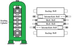
Sketch 10 is of a 6 high mill showing the position of the intermediate rolls. In the 6 high mill shown in sketch 10, the roll between the work roll and the corresponding back-up roll is called an intermediate roll.
These intermediate rolls have the ability to move horizontally slightly into or out of the mill stand. In so doing, the strip shape is affected. - Coolant distribution
Fine control of the strip's shape is achieved by adding a multi-zone header spraying water (either warm or cool) onto the work rolls at the exit of the last stand of a tandem mill.
However the problem still remained; that small errors in the strip's shape could not be seen while rolling due to the tension. - Shapemeter measurement and control
A variety of shapemeters have been developed. They are essentially multi-segment tension meters. There is the ASEA stressometer,[22] the Broner strainweb,[23] and the Davy-Mckee Vidimon air bearing shapemeter.[24]
These shapemeter rolls made it possible to measure the strip's shape and immediately adjust the appropriate zone(s) of the multi-zone spray header on the stand adjacent to the shapemeter roll; hence good shape control is achieved.[25]

Coil collapse

- patially slumped coil
- coil with kink into eye
- coil with sleeve and chocks
- coil with pseudo sleeve.
If a coil of thin strip is wound with low tension, then it may not have the strength to support itself and may collapse, especially if roughly handled,[26] see figure 1(a). A solution is to provide chocks to support the coils more appropriately.
If a large coil is wound with a high tension, then the tension stress builds up on the inner wraps and can cause them to kink,[27] as seen in figure 1(b). An early solution was to place a steel sleeve onto the tension reel mandrel before the coil started. However, loading the sleeve slowed production, and the handling of the sleeves back from the following production lines added an extra cost.
Figure 1(c) shows a coil with a sleeve sitting on chocks.
Industrial Automation Services devised a solution.[28] The early wraps are wound with a high tension to create a pseudo sleeve, then the body of the coil is wound with a moderate tension supported by that pseudo sleeve; as shown in figure 1(d).
Computers and HMI
In the 1980's it became possible for digital displays to replace hard-wired headboard-mimics and operator control/display panels.
The descriptions below are based on the upgrade of BlueScope Steel's 5 stand cold mill in 1985.
There are normally three levels of computers directly associated with a tandem rolling mill, as shown in sketch 11.

At the lowest level is a Programmable Logic Controller, PLC or minicomputer.
The PLC or minicomputer contains the control loops that run the rolling mill. It receives inputs into these dynamic controls directly from the hard-wired desk and gets the targets for the exit thickness, the tensions and the screw-down positions from the setup computer.
The desk controls include the speed requests (the thread, run and stop push buttons), any screw-down movements (each joystick has raise, lower, tilt left, and tilt right), and the tension trims (increase / decrease toggle switches).
Level 2 batch processing
At level 2 is a keyboard and screen having a menu-based interface into the setup computer's mill model. This operator interface is normally described as the Human Machine Interface, HMI. Through this interface the operator trims the setup for the next coil. He/she can trim the individual stand reductions, the inter-stand tensions, and the top speed as required. When the last stand has force control, then the rolling force can also be trimmed.
At this level there are a few TV monitors. At BlueScope Steel's cold mill these monitors included:
- A mimic of the process with digital displays of: the statuses (ON / OFF, running / stopped); the screw-down positions in mm in the top back-up rolls; the stand speeds in mpm in the bottom back-up rolls; the tension readings in kN adjacent to the tension rolls, and the diameter of the coil on tension reel.
- A display with collections of bar graphs grouped according to type: that is, the tensions, the rolling forces, and the currents in percent. This display also has a graph of the thickness error in percent.
Actually these displays can be connected to either level 1 or level 2; for example, after the more recent (in 1997) BlueScope Steel upgrade of their 6 stand hot strip mill, the operator displays are driven by the level 1 PLC's.
Level 3 supervision
The setup computer gets each coil's primary data from a scheduling computer. This scheduling computer usually receives the product's data from the previous production unit and will pass on the results of this mill's rolling to the next unit.
The primary data sent by the scheduling computer consists of the nominal entry thickness and width, the aim thickness, and if rolling a plate the aim width.
The scheduler assembles the coils or plates to be processed within each campaign using his/her Human Computer Interface, HCI terminal.
A campaign begins with a scheduled roll change; that is, when all of the work rolls of the tandem mill are changed together.
For a cold tandem mill, the campaign has a coffin-shaped width profile. The first few coils are about 3/4 of the full width. Gradually the coils become wider until the maximum product width is reached. This allows the thermal camber of the rolls to develop before rolling the full-width product. From then on the product becomes narrower, to avoid the excessive work roll wear corresponding to the strip edges.
Rolling mill definitions
.jpg)
These definition only apply to the rolling of slabs, plates and strip in a rolling mill.
Reduction
Reduction, r is defined as the per-unit change in thickness with respect to the entry thickness H, and so r = (H – h) / H where h is the exit thickness.[29][30]
As the material is reduced, its length becomes proportionately longer; this can be seen in the attached GIF movie.
There are many other definitions of the word reduction; such as in chemistry, medicine, surgery, safety, investment, and in a more general sense, such as in cooking and waste reduction, etc.
Elongation
When the reduction is small (<2%), it is normally referred to as an elongation or an extension.
Elongation, e is defined as the per-unit increase in length due to a decrease in area with respect to the entry, regardless of shape.
.jpg)

Given an entry length ℓ, then e = (L – ℓ) / ℓ where L is the final length.
If the width is unaffected (as is the case when rolling thin strip <2mm, see sketch 12), then the mass flow concept, gives H . ℓ = h . L
- Thus elongation, e = (H – h) / h
When the elongation is large it is normally measured as reduction, r which is defined as the per-unit change in thickness with respect to the entry thickness H; and so if h is the exit thickness,[29][30]
- Reduction, r = (H – h) / H
Note that the thickness difference (H – h) is divided by the exit thickness h for elongation and by the entry thickness H with reduction; so they are not identical.
An elongation of typically 1.3% is performed to eliminate the discontinuity (seen at the yield point in graph 6) in the stress verses strain reaction of thin steel strip[9] before it is tinned ready for making cans intended for containing preserved foods.
There are many other definitions of the word elongation; such as in astronomy, plasma physics, genetics, and in a more general sense, such as referring to the lengthening of an elastic band.
See also
- Deformation (engineering)
- Plasticity
- Steelmaking
- Steel mill
- Rolling (metalworking)
- Rolling Mill
- Work hardening
- Yield (engineering)
- Drawer slides roll forming machine
References
- ↑ Ray, S. (2015). Principles and Applications of Metal Rolling. Delhi, India: Cambridge University Press. p. 6. ISBN 978-1-107-07609-9.
- ↑ Wigman, S.L.; Millett, M.D. (November 1992). "Demands on refining processes in thin slab casting". Steel Times.
- ↑ Blejde, W.; Mahapatra, R.; Fukuse, H. (2000). "Development of Low Carbon Thin Strip Production Capability at Project 'M'". Iron and Steel 27 (4): 29–33.
- ↑ Wood, G.E.; Ivacheff, D.P. (January 1977). "Mill Modulus Variation and Hysteresis – Their Effects on Hot Strip Mill AGC". Iron and Steel Engineer: 29–33.
- ↑ 5.0 5.1 Carlton, A.J.; Edwards, W.J.; Thomas, P.J. (March 1977). "Formulae for Cold Rolling Analysis". Proc. AIME Annual Meeting: 238–248.
- ↑ Bland, D.R.; Ford, H. (1948). "The calculation of roll force and torque in cold strip rolling with tensions". Proceedings of the Institution of Mechanical Engineers 159: 144–163. doi:10.1243/PIME_PROC_1948_159_015_02.
- ↑ You, Changyu (2008). An Artificial Intelligence Model to Simulate Strip Flatness in a Tandem Cold Rolling Mill. School of Mechanical, Materials and Mechatronic Engineering (M.E.). University of Wollongong.
- ↑ DeGarmo, E. Paul (1962). Materials and Processes in Manufacturing (second ed.). New York: The Macmillan Company. p. 307.
- ↑ 9.0 9.1 9.2 DeGarmo, E. Paul (1962). Materials and Processes in Manufacturing (second ed.). New York: The Macmillan Company. pp. 15–18.
- ↑ Robertson, Gordon L. (2016). "Metal Packing Materials". Food Packaging: Principles and Practice (3 ed.). CRC Press. p. 191.
- ↑ DeGarmo, E. Paul (1962). Materials and Processes in Manufacturing (second ed.). New York: The Macmillan Company. pp. 22–23.
- ↑ Domanti, S.A.; Edwards, W.J.; Santarelli, M.J. (2003). "Head and tails in tandem rolling mills". Steel Times International (Redhill) 28 (1): 16–17,22.
- ↑ Ballyns, J. (1990). "Method and apparatus for the detection and correction of roll eccentricity in rolling mills". US Patent 4,910,985.
- ↑ Edwards, W.J.; Thomas, P.J.; Goodwin, G.C. (July 1987). "Roll Eccentricity Control for Strip Rolling Mills". IFAC Proceedings 20 (5, part 2): 187–198. doi:10.1016/S1474-6670(17)55438-5.
- ↑ Cockerell, R.A.; Edwards, W.J.; Spooner, P.D.; Thomas, P.J. (July 1993). "A Dynamic Rolling Mill Simulator for All Reasons". 26 (2.4). Sydney, Australia: International Federation of Automatic control. pp. 605–612.
- ↑ Cox, A. D. (March 2014). "Low speed thickness control for a temper mill". Australian Journal of Electrical & Electronics Engineering 11 (1): 87–92. doi:10.7158/E13-030.2014.11.1.
- ↑ Bryant, G.F.; Edwards, W.J.; Higham, J.D. (1973). "A Non-Interactive Control Structure". in Bryant, G.F.. Automation of Tandem Mills, Part 2. London: The Metals Society.
- ↑ 18.0 18.1 Avontuur, A.P.J. (March 2017). Maintenance Optimisation of Process Rolls, with an application to electrolytic tinning lines. School of Industrial Engineering (M.E.). Eindhoven University of Technology. pp. 21–22.
- ↑ Magura, D. (August 2019). "Distribution of the Strip Tensions with Slip Control in Strip Processing Lines". Energies, Switzerland: 3–6.
- ↑ Sheppard, T.; Roberts, M. (1973). "Shape Control and Correction in Strip and Sheet". International Metallurgical Reviews 9 (518): 1–18. doi:10.1179/imr.1973.18.1.1. Bibcode: 1973IMRv...18....1S.
- ↑ Edwards, W.J.; Johnston, P.W.; Phillips, I.D. (September 1976). "Roll Camber Design for Cold Rolling Mills". IFAC Proceedings Volumes 9 (5): 675–706. doi:10.1016/S1474-6670(17)67258-6.
- ↑ Crawford, C.W.J. (November 1992). "Instruments for Shape Control of Strip". Steel Times (London) 200 (11): 789–791.
- ↑ Duckworth, Sarah (September 1994). "New Generation of On-line Shape Measuring for Flat Rolling". Aluminium Today (Redhill) 6 (3): 33.
- ↑ Stubbs, S.G. (September 1983). "Strip into shape". Steel Times (London) 211 (9): 444,446–447.
- ↑ Olsson, Ulf (May 1991). "Approaching the absolute in flatness control of rolled strip". Steel Times International 15 (3): 45–46.
- ↑ Cozijnsen, M.; Yuen, W.Y.D. (January 1996). "Stress distributions in wound coils". Barton, ACT: Institution of Engineers, Australia. pp. 117–124.
- ↑ Wadsley, A.W.; Edwards, W.J. (1977). "Investigation of Tight-Center Coil Collapse". Metals 77.
- ↑ Domanti, S.; Edwards, W.J.; Voss, G.F. (2000). "Optimising coil winding". Steel Times 228 (3): 95–96.
- ↑ 29.0 29.1 Dr. Amr Shehata Fayed, Faculty of Engineering, Zagazig University. "Bulk Deformation Forming Processes". Flat Rolling Analysis slide 8. Charles Palmer. https://slideplayer.com/slide/4773790/.
- ↑ 30.0 30.1 Yuen, W.Y.D.; Dixon, A.; Nguyen, D.N. (1996). "The modelling of the mechanics of deformation in flat rolling". Journal of Materials Processing Technology 60 (1–4): 87–94. doi:10.1016/0924-0136(96)02312-6.
Further reading
- Sims, R.B., "The calculation of roll force and torque in hot rolling mills", Proceedings of the Institution of Mechanical Engineers, vol 168, no. 1, June 1954, pp 191-200.
- Lianis, G.; and Ford, H., "Control equations of multi-stand cold rolling mills", Proceedings of I.M.E., vol. 171, June 1957, pp 757-776.
- Bryant, G.F. (Editor); "Automation of Tandem Mills", The Iron & Steel Institute, London, 1973.
- Aeberli, K., "Combining the extended mass flow concept with eccentricity control for excellent gauge performance", Metals, Mining & More, Siemens, vol. 1, January 1997.
- Pittner, John; Simaan, Marwan A., "Tandem Cold Metal Rolling Mill Control using Practical Advanced Methods", Springer, London, 2010.
/ref> and the Davy-Mckee Vidimon air bearing shapemeter.
 |  |
