Engineering:Vacuum filler
This article has multiple issues. Please help improve it or discuss these issues on the talk page. (Learn how and when to remove these template messages)
(Learn how and when to remove this template message) |
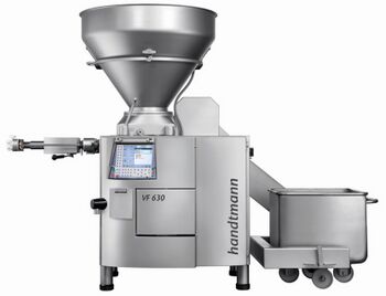
A vacuum filler is a machine used for filling pasty products.[1] The pasty products are moved with the aid of a vane cell feed system under a vacuum.
Objective
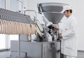
Levelling the weight of pre-packaged goods in the food sector, especially those involving viscous or pasty products, places extremely high demands on the reproducible accuracy of filling and portioning systems. In order to achieve this, technical and technological issues as well as product-specific characteristics have to be taken into account. In addition to the aforementioned factors, the requirements on the quality of an end product is a key issue when selecting or implementing a technical process solution. The development of vacuum filling machines has made it possible to fulfill both the technical and the quality-related requirements.
In the food sector, moving or transporting fluids is achieved with the aid of pump technology. Colloquially, this is known as filling or portioning. Various different types of pumps are used, depending on the type of filling products to be moved. Vacuum fillers with vane cell feed systems and vacuum feeding are commonly used for viscous products. The products are transported with the aid of a hopper with a feeding device, a vane cell feed system under a vacuum and appropriate volume expulsion in the pump housing. This is basically a volumetric feed principle, which means that a certain weight is defined via a volume. In addition to the vane cell feed systems,[2] also known as rotary vane pumps, there are also screw feed systems with feed augers, toothed wheel feed systems and evacuated lifting cylinders. With all these systems, transportation is achieved via volume expulsion under a vacuum. Vacuum fillers are traditionally used in the meat processing industry as well as in other food sectors. They can also be found in some non-food sectors. Generally speaking, vacuum fillers can be used for filling pasty and compressible products.
History
The first vacuum filler was developed in the early 1960s. The technology has been refined since then.
Requirements/effects
The pumpability of viscous or pasty products has a key effect on the reliable function of a vacuum filler. Filling products in the food sector can be characterised with the aid of various different properties related to their pumpability (“fillability”). They are either physical characteristics that can be measured directly or they are sensory attributes.
- Gas content/density
- The gas content is also called the “air content”. The air content of a fluid is the percentage share of air that enters the fluid during grinding/mixing processes. This can be measured using special apparatus and has a direct relationship to the density of a fluid.
- Compressibility
- The compressibility depends on the air content of a fluid. A high level of compressibility is linked to a high gas content in the fluid.
- Viscosity
- Viscosity is a measure of the consistency of a fluid. The higher the viscosity, the higher the consistency of the fluid is (it is less fluid); the lower the viscosity, the lower the consistency of it is (more fluid). Highly-viscous filling products in the food processing industry are primarily found in the meat, bakery products and convenience food sectors. These highly-viscous substances are commonly referred to as being “pasty”. The fluidity is the basic requirement for the pumpability of a fluid. The viscosity can also be determined using suitable rheological measuring apparatus. In the food sector, the viscosity is primarily dependent on the fluid content of the filling product.
- Temperature
- The temperature is a key factor for pumpability as it has a direct effect on the viscosity as well as on the product quality.
- Texture, fibrousness, dimensions of the inserts
- Specific sensory characteristics of a filling product have a significant effect on the assessment of the fillability and compliance with the precise weight.
- Weight accuracy
- With the help of modern filling technology in the food sector, accurate portioning with a difference of up to 1% in relation to the required volume of a portion can be achieved.
Mode of operation
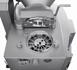
The key element of a vacuum filler is the vacuum filling principle. The filling product is fed into the feed system mechanically via a hopper with actively driven feeding auger, as well as via vertical “vacuum suction”. Pre-evacuated cells of a vane cell feed system move underneath the hopper. The pressure difference relative to the ambient pressure (underpressure) caused by the evacuation ensures that the cells are filled with product. The feed system moves continuously, thus generating a continuous filling flow. The product is portioned by means of cyclic movements of the feed system. Each cell of the feed system has a particular volume. The portion is defined by the rotation distance of the rotor. The portioning volume is therefore set in the control system by multiplying the rotor's rotation distance by the number of the feed system cells within it. The portion weight must be determined in the control system via the portion volume parameter with the aid of scales.
Structure and technical requirements
Vacuum fillers are primarily used in the food trade and in the food industry. Special criteria apply to the design of machines in the food sector due to specific hygiene standards and hygiene regulations. This includes, for example, ensuring that they are easy to dismantle, have level surfaces and seals that can be rinsed from the rear, no dead spaces, ergonomic shapes, a small range of parts and detectable materials/materials suitable for food use. Relatively aggressive ambient conditions, such as reactive detergents, reactive or abrasive filling media, intensive high-pressure cleaning and extreme ambient temperatures, are also faced.
Vacuum fillers are therefore made of a high proportion of stainless steel with a very robust design. Moving parts can be easily dismantled and can be cleaned individually. In addition to the mechanical or design-related issues, complex electronic components in a vacuum filler also have to be taken into account.
Vane cell feed system with hopper
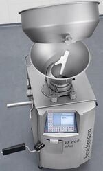
The vane cell feed system mainly consists of a rigid pump housing with attached side plate that is fixed to the pivoting hopper, and a removable rotor with pump vanes and cam. Depending on the machine size there are various different sizes of vane cell feed systems with parts with appropriate dimensions. The hopper can be swivelled to clean and dismantle surfaces and parts that come into contact with filling product. The driven rotor with an appropriate number of slots is located in the pump housing, in which pump vanes form cells with defined volumes when the machine is closed, supported by the cam. Induced by the rotor movement when the machine is started, the cells move in the direction of the vane cell feed system outlet and therefore ensure that a defined product flow is achieved. The weight accuracy of a feed system is partially dependent upon the production precision of the parts and their degree of wear.
Vacuum system
The cells are filled by evacuating the vane cell feed system. By applying a vacuum via a vacuum pump, the filling products are gently drawn out of the hopper into the feed system as soon as an evacuated cell moves underneath the hopper. The vacuum pump is protected by an integrated water separator. The level of vacuum can be set according to the filling product. In addition to the feed effect, the filling product is simultaneously evacuated to a certain extent (approx. 2–4 %). This means that the air content of the filling product decreases and the filling product becomes denser.
Feeding
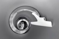
The term feeding in the context of vacuum fillers refers to actively moving the filling media in the direction of the lower part of the hopper to support the vacuum approach within the hopper. Feeding is achieved by using moveable feeding augers with scrapers/rigid counter arms. The feeding auger is driven in synchronisation with the rotation of the rotors. Due to the special geometry of both augers and the parallel rotation movement, the filling product is moved vertically in the direction of the vane cell feed system. The required feed intensity depends on the viscosity of the media to be filled. Less active feed is needed with low-viscosity media than with high-viscosity product. There are therefore a variety of combinations or versions of the parts involved in the feeding process.
Machine base
The machine base acts as the stand for a vacuum filler. For hygiene reasons, bases are made completely of stainless steel. The compact machine base is designed to ensure that it can be moved easily using lifting equipment.
Lifting device
Lifting devices allow the hopper to be loaded using standard trolleys. They can either be fixed onto the vacuum filler or a mast type lifting device can be positioned separately next to the vacuum filler. Lifting devices can be driven hydraulically or electrically.
Control and drive systems
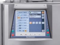
A computer-aided control system is required for operating the various functions associated with a vacuum filler. Usually, several drives are integrated into the vacuum fillers for the various different applications. With the most modern generations of vacuum fillers, the drives are implemented by means of servo motors and appropriate bus systems.
Sealing devices
To produce individual portions from homogeneous product via a feed system, a “sealing device” is always required at the feed system outlet. This device separates portions and is controlled in synchronisation with the portion output. These devices could be linking devices for sausages, clippers for portionable sausages, dosing valves for tubs and cans, cutting devices for dough as well as forming equipment for dumplings.
Other feed system principles
Generally speaking, vacuum fillers can be equipped with various different feed systems. However, in principle, the basic machine structure, with a hopper, vacuum system, feeding device, machine base, lifting device, control system and sealing device, is very similar. Depending on the application, each type of feed system has advantages and disadvantages.
- Screw feed system with feed augers
- With a screw feed system, two counter-rotating screws form cells within a housing; they are moved in the direction of the pump when the screws are rotated. The filling product is again moved into the screw feed system with the aid of a vacuum and mechanical feeding devices.
- Toothed wheel feed system
- An outer toothed ring is driven, rotating an inner toothed wheel with it. The toothed wheels form cell segments as they move against each other. The cell content is transported through the toothing and it is then voided and ejected in the outlet area.
- Feeding via lifting cylinders
- Feeding via alternately moving lifting cylinders is the simplest feed system principle. The volume is defined by the geometry of the cylinders, and the portion size is determined by the number of strokes.
- Hopper vacuum systems
- The additional creation of a hopper vacuum is a variation of the vacuum filler concept. The vacuum system is enhanced with an additional vacuum pump, specially designed for the hopper. The hopper is closed and is connected to an upstream reservoir. The vacuum present in the hopper allows filling product to be drawn into the filling machine from the reservoir. The filling product is also intensively evacuated.
Range of applications
Food
- Meat products
- Cooked, dry and boiled sausage (sausage meat)
- Dry and cooked cured products
- Dairy products
- Butter
- Cream cheese and cream cheese-based products
- Curd
- Cheese spread products
- Yoghurt
- Fish products
- Fish masses
- Caviar
- Vegetable products
- Potato products
- Bakery products
- Fruit bread
- Cake mixtures
- Pasta
- Turnovers
- Pasta dough
- Confectionery
- Marzipan
- Chocolate products
- Blancmange-type products
- Delicatessen products
- Soups
- Sauces
- Spiced marinades
- Delicatessen salads
- Raw fruit and vegetable products with fibrous inserts
- All types of fillings
Chemicals and non-food products
- TNT
- Technical sealants
Problems and their solutions
Many problems may occur when filling viscous media. The problems are often product-specific and are revealed when the product to be filled takes on an a-typical appearance. Examples of this are an inhomogeneous product appearance with sausage goods or when inserts are ground too finely during the pumping process. However commercial or legal problems can also arise, in the form of weight deviations or non-compliance with the specified quality regulations (e.g. the guidelines for meat products).
These problems are caused by a variety of influences, such as air content or viscosity being too high, insufficient feed volume in the feed system, temperature-related influences and mechanical influences such as friction and fragmentation. The aforementioned problems can be eradicated by modifying upstream process steps, adapting recipes and making technical modifications.
Auxiliary devices
- Holding devices
- Holding devices in the field of sausage production are used for automatic sausage linking. A holding device comprises a rotating linking nozzle and an appropriate sausage casing brake. The movement of the linking nozzle is achieved by a drive integrated into the vacuum filler. The sausage casing brake ensures that the sausage casings are extracted evenly, thus creating equal portions.
- Hanging lines
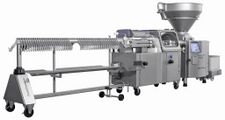
Hanging lines in the field of sausage production are auxiliary devices for linking and hanging portions of sausage. In principle, the application is similar to that of a holding device, however significantly higher filling capacities can be achieved. Hanging lines are available with various different degrees of automation.
- Cutting lines
- Cutting lines in the field of sausage production have the same basic structure as hanging lines. Cutting lines are used to chop linked strings of sausages into portioned sausages.
- Clippers
- Clippers for the production of portioned sausages are used in conjunction with vacuum fillers. The filling product is taken from the vacuum filler and through a filling pipe connected to the clipper and an appropriate sausage casing brake, where it is portioned into appropriate casings. The portion is then sealed by the clipper with the aid of metal clips. Sometimes, loops for hanging the portions are also attached simultaneously. Strings of sausages as well as individual portions can be produced.
- Forming devices
- Forming devices are used for the production of formed products, such as dumplings and burgers. There are two types. With free-forming devices, the filling product is filled via tubing with an attached separating device. The separating device and the portion output are synchronised in such a way that it is possible to form the filling flow. The separating devices can be diaphragms[3][4](which function in a similar way to a photographic iris diaphragm; opening and closing creates a round shape during portioning), forming blades that move against each other or simple wire cutters or blades. The portion is ejected when the separating unit is opened. The separating devices then close in synchronisation with the end of the portion. This synchronised, adjustable process allows various different shapes to be created. The products can be directly transported for packaging or for thermal treatment on conveyor belts. With devices with forming dies, the filling product is filled into forming dies (plastic mould that is filled to the base). The filled mould is “moved” away from the filling area, it is detached from the flow of product by means of a simultaneous clipping movement and then ejected mechanically or pneumatically into transportation containers or into thermal treatment media.
- Co-extrusion systems
- Co-extrusion means the synchronous feeding of two or more product flows with the aim of producing filled products (e.g. meatballs with ketchup filling, sausages with mustard filling and potato dumplings with a meat filling). Two or more vacuum fillers are always required. Co-extrusion systems are available for the forming, clipping and linking applications.
- ConPro systems
- ConPro systems (continuous production systems) are special continuous co-extrusion systems for producing sausages with alginate skin. With this application, two vacuum fillers are operated in synchronisation and their filling flows are combined into one continuous product flow. Further down the process, the continuous string is divided into individual portions or strings of portions. One vacuum filler pumps the filling product while a second one deposits the skin (a paste containing alginate) via an annular gap. This is solidified by means of a fixing solution containing calcium ions. Depending on the degree of automation, the portions can be hung or collated or transported further for continuous thermal treatment or packaging. The most important advantage of the ConPro systems in comparison to traditional production methods is that sausage skins or casings no longer have to be changed. Due to continuous co-extrusion there are no casing change times and therefore the filling time is maximised.
- Inline grinding systems
- In the meat processing industry, grinding systems are used for grinding meat and are to be found ahead of the filling process in the product preparation phase. With inline grinding systems, a grinding system is integrated into the vacuum filler's filling flow as an auxiliary device. The filling and grinding process steps can therefore be combined in a single machine. This means that the filling product is moved by the vacuum filler and, during filling, it is chopped to the final grain size within the grinding system. An important application for inline grinding systems is dry sausage or fresh sausage production.
- Minced meat lines
- Minced meat lines are a combination of vacuum fillers, inline grinding systems and devices for separating the minced meat flow into individual portions. A continuous, formed product flow is filled onto a conveyor belt and a cutting blade divides the filling flow into portions. The portions can then be packed straight away.
- Filling flow dividers
- A filling flow divider can separate a single product flow from a pump into several equal flows. Feed systems similar to a vane cell feed system are integrated into filling flow dividers. Filling flow dividers are required, for example, for simultaneous depositing into several containers.
- Valves
- Valves or cutting devices are used as sealing devices at the end of tubing or filling flow dividers.
Weight control and process documentation
Multi-machine electronic control and documentation systems are used to document a filling process involving vacuum fillers or to monitor filling weights.
See also
References
- ↑ "Verfahren und Vakuumfüller zum Abfüllen einer pastösen Masse" Retrieved August 8, 2012
- ↑ „Flügelzellenpumpe“ , Retrieved August 8, 2012
- ↑ „Diaphragma“ , Retrieved August 8, 2012
- ↑ "Excavator Auger". https://web.archive.org/web/20160303232932/http://www.patent-de.com/20020502/EP0718497.html.
 |
