Engineering:Wax thermostatic element

The wax thermostatic element was invented in 1934 by Sergius Vernet (1899–1968).[1] Its principal application is in automotive thermostats used in the engine cooling system. The first applications in the plumbing and heating industries were in Sweden (1970) and in Switzerland (1971).
Wax thermostatic elements transform heat energy into mechanical energy using the thermal expansion of waxes when they melt. This wax motor principle also finds applications besides engine cooling systems, including heating system thermostatic radiator valves, plumbing, industrial, and agriculture.
Automotive thermostats
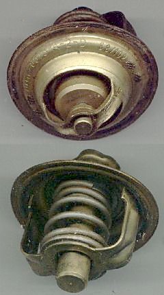
The internal combustion engine cooling thermostat maintains the temperature of the engine near its optimum operating temperature by regulating the flow of coolant to an air cooled radiator. This regulation is now carried out by an internal thermostat. Conveniently, both the sensing element of the thermostat and its control valve may be placed at the same location, allowing the use of a simple self-contained non-powered thermostat as the primary device for the precise control of engine temperature.[2] Although most vehicles now have a temperature-controlled electric cooling fan, "the unassisted air stream can provide sufficient cooling up to 95% of the time"[3] and so such a fan is not the mechanism for primary control of the internal temperature.
Research in the 1920s showed that cylinder wear was aggravated by condensation of fuel when it contacted a cool cylinder wall which removed the oil film. The development of the automatic thermostat in the 1930s solved this problem by ensuring fast engine warm-up.[4]
The first thermostats used a sealed capsule of an organic liquid with a boiling point just below the desired opening temperature. These capsules were made in the form of a cylindrical bellows. As the liquid boiled inside the capsule, the capsule bellows expanded, opening a sheet brass plug valve within the thermostat.[5][6] As these thermostats could fail in service, they were designed for easy replacement during servicing, usually by being mounted under the water outlet fitting at the top of the cylinder block. Conveniently this was also the hottest accessible part of the cooling circuit, giving a fast response when warming up.
Cooling circuits have a small bypass path even when the thermostat is closed, usually by a small hole in the thermostat. This allows enough flow of cooling water to heat the thermostat when warming up. It also provided an escape route for trapped air when first filling the system. A larger bypass is often provided, through the cylinder block and water pump, so as to keep the rising temperature distribution even.[5]
Work on cooling high-performance aircraft engines in the 1930s led to the adoption of pressurised cooling systems, which became common on post-war cars. As the boiling point of water increases with increasing pressure, these pressurised systems could run at a higher temperature without boiling. This increased both the working temperature of the engine, thus its efficiency, and also the heat capacity of the coolant by volume, allowing smaller cooling systems that required less pump power.[6] A drawback to the bellows thermostat was that it was also sensitive to pressure changes, thus could sometimes be forced shut again by pressure, leading to overheating.[6] The later wax pellet type has a negligible change in its external volume, thus is insensitive to pressure changes.[6] It is otherwise identical in operation to the earlier type. Many cars of the 1950s, or earlier, that were originally built with bellows thermostats were later serviced with replacement wax capsule thermostats, without requiring any change or adaption.
This most common modern form of thermostat now uses a wax pellet inside a sealed chamber.[6] Rather than a liquid-vapour transition, these use a solid-liquid transition, which for waxes is accompanied by a large increase in volume. The wax is solid at low temperatures, and as the engine heats up, the wax melts and expands. The sealed chamber operates a rod which opens a valve when the operating temperature is exceeded. The operating temperature is fixed, but is determined by the specific composition of the wax, so thermostats of this type are available to maintain different temperatures, typically in the range of 70 to 90°C (160 to 200°F).[7] Modern engines run hot, that is, over 80 °C (180 °F), in order to run more efficiently and to reduce the emission of pollutants.
While the thermostat is closed, there is no flow of coolant in the radiator loop, and coolant water is instead redirected through the engine, allowing it to warm up rapidly while also avoiding hot spots. The thermostat stays closed until the coolant temperature reaches the nominal thermostat opening temperature. The thermostat then progressively opens as the coolant temperature increases to the optimum operating temperature, increasing the coolant flow to the radiator. Once the optimum operating temperature is reached, the thermostat progressively increases or decreases its opening in response to temperature changes, dynamically balancing the coolant recirculation flow and coolant flow to the radiator to maintain the engine temperature in the optimum range as engine heat output, vehicle speed, and outside ambient temperature change. Under normal operating conditions the thermostat is open to about half of its stroke travel, so that it can open further or reduce its opening to react to changes in operating conditions. A correctly designed thermostat will never be fully open or fully closed while the engine is operating normally, or overheating or overcooling would occur.

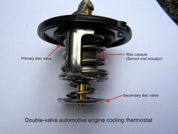
Engines which require a tighter control of temperature, as they are sensitive to "Thermal shock" caused by surges of coolant, may use a "constant inlet temperature" system. In this arrangement the inlet cooling to the engine is controlled by double-valve thermostat which mixes a re-circulating sensing flow with the radiator cooling flow. These employ a single capsule, but have two valve discs. Thus a very compact, and simple but effective, control function is achieved.
The double-valve thermostat may also regulate the flow of coolant to the carburettor: as long as the temperature of the coolant is relative low, the carburettor will be warmed up, so further speeding up the warming up of the engine.
The wax used within the thermostat is specially manufactured for the purpose. Unlike a standard paraffin wax, which has a relatively wide range of carbon chain lengths, a wax used in the thermostat application has a very narrow range of carbon molecule chains. The extent of the chains is usually determined by the melting characteristics demanded by the specific end application. To manufacture a product in this manner requires very precise levels of distillation.
Types of elements
Flat diaphragm element
The temperature sensing material contained in the cup transfers pressure to the piston by means of the diaphragm and the plug, held tightly in position by the guide. On cooling, the initial position of the piston is obtained by means of a return spring. Flat diaphragm elements are particularly noted for their high level of accuracy, and therefore mainly used in sanitary installations and heating.
Squeeze-push elements
Squeeze-Push elements contain a synthetic rubber sleeve-like component shaped like the 'finger of a glove' which surrounds the piston. As the temperature increases, pressure from the expansion of the thermostatic material moves the piston with a lateral squeeze and a vertical push. As with the flat diaphragm element, the piston returns to its initial position by means of a return spring. These elements are slightly less accurate but provide a longer stroke.
Properties
The stroke is the movement of the piston in relation to its starting point. The ideal stroke corresponds to the temperature range of the elements. According to the type of element, it can vary from 1.5 mm to 16 mm.
The temperature range lies between the minimum and maximum operating temperature of the element. Elements can cover temperatures ranging from -15 °C to +120 °C. Elements may move in proportion to the temperature change over some part of the range, or may open suddenly around a particular temperature depending on the composition of the waxes.[citation needed]
Hysteresis is the difference noted between the upstroke and down stroke curve on heating and cooling of the element. Hysteresis is caused by the thermal inertia of the element and by the friction between the parts in motion.[8]
See also
References
- ↑ Vernet, Sergius "Thermostat," U.S. Patent no. 2,115,501 (filed: 1934 October 1; issued: 1938 April 26).
- ↑ "Engine cooling". Automotive Handbook (3rd ed.). Bosch. 1993. p. 413. ISBN 0-8376-0330-7. "It is recommended that a temperature-sensitive thermostat incorporating an expansion element be installed to regulate temperature"
- ↑ Bosch & Automotive Handbook, p. 414
- ↑ Sir Harry Ricardo - Memories and machines: the pattern of my life Constable, London, 1968. P218
- ↑ 5.0 5.1 Know Your Car (5th ed.). Autocar. 1957. pp. 57–58.
- ↑ 6.0 6.1 6.2 6.3 6.4 Setright, L. J. K. (1976). "Cooling". in Ian Ward. Anatomy of the Motor Car. Orbis. pp. 61–62. ISBN 0-85613-230-6.
- ↑ Don Knowles, Jack Erjavec Basic automotive service and maintenance Cengage Learning, 2004 ISBN 1-4018-5208-4 page 140
- ↑ "Hysteresis Curve Diagram". Rostra Vernatherm. 2011. http://www.vernatherm.com/thermal-actuators.htm.
External links
- Vernatherm - Thermal Actuators - and other Thermostatic Fluid Controls - Rostra Vernatherm
- ThermalActuators.com - Thermal Actuators - & Mechanical Function Information & Products - Thermal Actuators
- Vernet.fr - Thermostatic Elements Cartridges Thermostats Electrothermic Actuator
- Raymot.com - Wax thermostatic elements page
- Ysnews.com - Vernet founded leading Yellow Springs company
- Vernay - 1946 Vernet founded Vernay Laboratories
- thermal-actuators.com - Automotive | TU-POLY
 |
