Physics:Kinematic chain


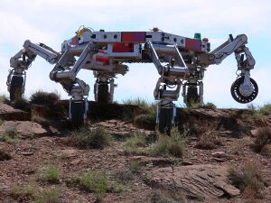
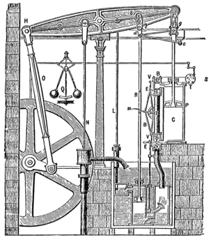
In mechanical engineering, a kinematic chain is an assembly of rigid bodies connected by joints to provide constrained motion that is the mathematical model for a mechanical system.[1] As the word chain suggests, the rigid bodies, or links, are constrained by their connections to other links. An example is the simple open chain formed by links connected in series, like the usual chain, which is the kinematic model for a typical robot manipulator.[2]
Mathematical models of the connections, or joints, between two links are termed kinematic pairs. Kinematic pairs model the hinged and sliding joints fundamental to robotics, often called lower pairs and the surface contact joints critical to cams and gearing, called higher pairs. These joints are generally modeled as holonomic constraints. A kinematic diagram is a schematic of the mechanical system that shows the kinematic chain.
The modern use of kinematic chains includes compliance that arises from flexure joints in precision mechanisms, link compliance in compliant mechanisms and micro-electro-mechanical systems, and cable compliance in cable robotic and tensegrity systems.[3] [4]
Mobility formula
The degrees of freedom, or mobility, of a kinematic chain is the number of parameters that define the configuration of the chain.[2][5] A system of n rigid bodies moving in space has 6n degrees of freedom measured relative to a fixed frame. This frame is included in the count of bodies, so that mobility does not depend on link that forms the fixed frame. This means the degree-of-freedom of this system is M = 6(N − 1), where N = n + 1 is the number of moving bodies plus the fixed body.
Joints that connect bodies impose constraints. Specifically, hinges and sliders each impose five constraints and therefore remove five degrees of freedom. It is convenient to define the number of constraints c that a joint imposes in terms of the joint's freedom f, where c = 6 − f. In the case of a hinge or slider, which are one-degree-of-freedom joints, have f = 1 and therefore c = 6 − 1 = 5.
The result is that the mobility of a kinematic chain formed from n moving links and j joints each with freedom fi, i = 1, 2, …, j, is given by
Recall that N includes the fixed link.
Analysis of kinematic chains
The constraint equations of a kinematic chain couple the range of movement allowed at each joint to the dimensions of the links in the chain, and form algebraic equations that are solved to determine the configuration of the chain associated with specific values of input parameters, called degrees of freedom.
The constraint equations for a kinematic chain are obtained using rigid transformations [Z] to characterize the relative movement allowed at each joint and separate rigid transformations [X] to define the dimensions of each link. In the case of a serial open chain, the result is a sequence of rigid transformations alternating joint and link transformations from the base of the chain to its end link, which is equated to the specified position for the end link. A chain of n links connected in series has the kinematic equations,
where [T] is the transformation locating the end-link—notice that the chain includes a "zeroth" link consisting of the ground frame to which it is attached. These equations are called the forward kinematics equations of the serial chain.[6]
Kinematic chains of a wide range of complexity are analyzed by equating the kinematics equations of serial chains that form loops within the kinematic chain. These equations are often called loop equations.
The complexity (in terms of calculating the forward and inverse kinematics) of the chain is determined by the following factors:
- Its topology: a serial chain, a parallel manipulator, a tree structure, or a graph.
- Its geometrical form: how are neighbouring joints spatially connected to each other?
Explanation
Two or more rigid bodies in space are collectively called a rigid body system. We can hinder the motion of these independent rigid bodies with kinematic constraints. Kinematic constraints are constraints between rigid bodies that result in the decrease of the degrees of freedom of rigid body system.[5]
Synthesis of kinematic chains
The constraint equations of a kinematic chain can be used in reverse to determine the dimensions of the links from a specification of the desired movement of the system. This is termed kinematic synthesis.[7]
Perhaps the most developed formulation of kinematic synthesis is for four-bar linkages, which is known as Burmester theory.[8][9][10]
Ferdinand Freudenstein is often called the father of modern kinematics for his contributions to the kinematic synthesis of linkages beginning in the 1950s. His use of the newly developed computer to solve Freudenstein's equation became the prototype of computer-aided design systems.[7]
This work has been generalized to the synthesis of spherical and spatial mechanisms.[2]
See also
- Assur group
- Denavit–Hartenberg parameters
- Chebychev–Grübler–Kutzbach criterion
- Configuration space
- Machine (mechanical)
- Mechanism (engineering)
- Six-bar linkage
- Simple machines
- Six degrees of freedom
- Superposition principle
References
- ↑ Reuleaux, F., 1876 The Kinematics of Machinery, (trans. and annotated by A. B. W. Kennedy), reprinted by Dover, New York (1963)
- ↑ 2.0 2.1 2.2 J. M. McCarthy and G. S. Soh, 2010, Geometric Design of Linkages, Springer, New York.
- ↑ Larry L. Howell, 2001, Compliant mechanisms, John Wiley & Sons.
- ↑ Alexander Slocum, 1992, Precision Machine Design, SME
- ↑ 5.0 5.1 J. J. Uicker, G. R. Pennock, and J. E. Shigley, 2003, Theory of Machines and Mechanisms, Oxford University Press, New York.
- ↑ J. M. McCarthy, 1990, Introduction to Theoretical Kinematics, MIT Press, Cambridge, Massachusetts.
- ↑ 7.0 7.1 R. S. Hartenberg and J. Denavit, 1964, Kinematic Synthesis of Linkages, McGraw-Hill, New York.
- ↑ Suh, C. H., and Radcliffe, C. W., Kinematics and Mechanism Design, John Wiley and Sons, New York, 1978.
- ↑ Sandor, G.N., and Erdman, A.G., 1984, Advanced Mechanism Design: Analysis and Synthesis, Vol. 2. Prentice-Hall, Englewood Cliffs, NJ.
- ↑ Hunt, K. H., Kinematic Geometry of Mechanisms, Oxford Engineering Science Series, 1979
 |
