Chemistry:Solder
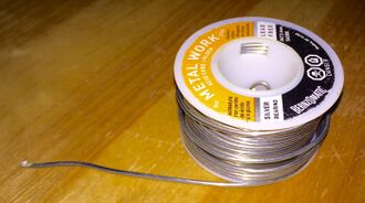
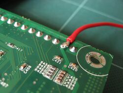
Solder (UK: /ˈsɒldə, ˈsəʊldə/;[1] NA: /ˈsɒdər/)[2] is a fusible metal alloy used to create a permanent bond between metal workpieces. Solder is melted in order to wet the parts of the joint, where it adheres to and connects the pieces after cooling. Metals or alloys suitable for use as solder should have a lower melting point than the pieces to be joined. The solder should also be resistant to oxidative and corrosive effects that would degrade the joint over time. Solder used in making electrical connections also needs to have favorable electrical characteristics.
Soft solder typically has a melting point range of 90 to 450 °C (190 to 840 °F; 360 to 720 K),[3] and is commonly used in electronics, plumbing, and sheet metal work. Alloys that melt between 180 and 190 °C (360 and 370 °F; 450 and 460 K) are the most commonly used. Soldering performed using alloys with a melting point above 450 °C (840 °F; 720 K) is called "hard soldering", "silver soldering", or brazing.
In specific proportions, some alloys are eutectic — that is, the alloy's melting point is the lowest possible for a mixture of those components, and coincides with the freezing point. Non-eutectic alloys can have markedly different solidus and liquidus temperatures, as they have distinct liquid and solid transitions. Non-eutectic mixtures often exist as a paste of solid particles in a melted matrix of the lower-melting phase as they approach high enough temperatures. In electrical work, if the joint is disturbed while in this "pasty" state before it fully solidifies, a poor electrical connection may result; use of eutectic solder reduces this problem. The pasty state of a non-eutectic solder can be exploited in plumbing, as it allows molding of the solder during cooling, e.g. for ensuring watertight joint of pipes, resulting in a so-called "wiped joint".
For electrical and electronics work, solder wire is available in a range of thicknesses for hand-soldering (manual soldering is performed using a soldering iron or soldering gun), and with cores containing flux. It is also available as a room temperature paste, as a preformed foil shaped to match the workpiece which may be more suited for mechanized mass-production, or in small "tabs" that can be wrapped around the joint and melted with a flame where an iron isn't usable or available, as for instance in field repairs. Alloys of lead and tin were commonly used in the past and are still available; they are particularly convenient for hand-soldering. Lead-free solders have been increasing in use due to regulatory requirements plus the health and environmental benefits of avoiding lead-based electronic components. They are almost exclusively used today in consumer electronics.[4]
Plumbers often use bars of solder, much thicker than the wire used for electrical applications, and apply flux separately; many plumbing-suitable soldering fluxes are too corrosive (or conductive) to be used in electrical or electronic work. Jewelers often use solder in thin sheets, which they cut into snippets.
Etymology
The word solder comes from the Middle English word soudur, via Old French solduree and soulder, from the Latin solidare, meaning "to make solid".[5]
Composition
Lead-based
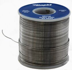
60Pb
40 solder
Tin-lead (Sn-Pb) solders, also called soft solders, are commercially available with tin concentrations between 5% and 70% by weight. The greater the tin concentration, the greater the solder's tensile and shear strengths. Lead mitigates the formation of tin whiskers,[6] though the precise mechanism for this is unknown.[7] Today, many techniques are used to mitigate the problem, including changes to the annealing process (heating and cooling), addition of elements like copper and nickel, and the application of conformal coatings.[8] Alloys commonly used for electrical soldering are 60/40 Sn-Pb, which melts at 188 °C (370 °F),[9] and 63/37 Sn-Pb used principally in electrical/electronic work. The latter mixture is a eutectic alloy of these metals, which:
- has the lowest melting point (183 °C or 361 °F) of all the tin-lead alloys; and
- the melting point is truly a point — not a range.
In the United States, since 1974, lead is prohibited in solder and flux in plumbing applications for drinking water use, per the Safe Drinking Water Act.[10] Historically, a higher proportion of lead was used, commonly 50/50. This had the advantage of making the alloy solidify more slowly. With the pipes being physically fitted together before soldering, the solder could be wiped over the joint to ensure water tightness. Although lead water pipes were displaced by copper when the significance of lead poisoning began to be fully appreciated, lead solder was still used until the 1980s because it was thought that the amount of lead that could leach into water from the solder was negligible from a properly soldered joint. The electrochemical couple of copper and lead promotes corrosion of the lead and tin. Tin, however, is protected by insoluble oxide. Since even small amounts of lead have been found detrimental to health as a potent neurotoxin,[11] lead in plumbing solder was replaced by silver (food-grade applications) or antimony, with copper often added, and the proportion of tin was increased (see lead-free solder).
The addition of tin—more expensive than lead—improves wetting properties of the alloy; lead itself has poor wetting characteristics. High-tin tin-lead alloys have limited use as the workability range can be provided by a cheaper high-lead alloy.[12]
Lead-tin solders readily dissolve gold plating and form brittle intermetallics.[13] 60/40 Sn-Pb solder oxidizes on the surface, forming a complex 4-layer structure: tin(IV) oxide on the surface, below it a layer of tin(II) oxide with finely dispersed lead, followed by a layer of tin(II) oxide with finely dispersed tin and lead, and the solder alloy itself underneath.[14]
Lead, and to some degree tin, as used in solder contains small but significant amounts of radioisotope impurities. Radioisotopes undergoing alpha decay are a concern due to their tendency to cause soft errors. Polonium-210 is especially troublesome; lead-210 beta decays to bismuth-210 which then beta decays to polonium-210, an intense emitter of alpha particles. Uranium-238 and thorium-232 are other significant contaminants of alloys of lead.[15][16]
Lead-free
The European Union Waste Electrical and Electronic Equipment Directive and Restriction of Hazardous Substances Directive were adopted in early 2003 and came into effect on July 1, 2006, restricting the inclusion of lead in most consumer electronics sold in the EU, and having a broad effect on consumer electronics sold worldwide. In the US, manufacturers may receive tax benefits by reducing the use of lead-based solder. Lead-free solders in commercial use may contain tin, copper, silver, bismuth, indium, zinc, antimony, and traces of other metals. Most lead-free replacements for conventional 60/40 and 63/37 Sn-Pb solder have melting points from 50 to 200 °C higher,[17] though there are also solders with much lower melting points. Lead-free solder typically requires around 2% flux by mass for adequate wetting ability.[18]
When lead-free solder is used in wave soldering, a slightly modified solder pot may be desirable (e.g. titanium liners or impellers) to reduce maintenance cost due to increased tin-scavenging of high-tin solder.
Lead-free solder is prohibited in critical applications, such as aerospace, military and medical projects, because joints are likely to suffer from metal fatigue failure under stress (such as that from thermal expansion and contraction). Although this is a property that conventional leaded solder possesses as well (like any metal), the point at which stress fatigue will usually occur in leaded solder is substantially above the level of stresses normally encountered.
Tin-silver-copper (Sn-Ag-Cu, or SAC) solders are used by two-thirds of Japanese manufacturers for reflow and wave soldering, and by about 75% of companies for hand soldering. The widespread use of this popular lead-free solder alloy family is based on the reduced melting point of the Sn-Ag-Cu ternary eutectic behavior (217 °C (423 °F)*), which is below the 22/78 Sn-Ag (wt.%) eutectic of 221 °C (430 °F) and the 99.3/0.7 Sn-Cu eutectic of 227 °C (441 °F).[19] The ternary eutectic behavior of Sn-Ag-Cu and its application for electronics assembly was discovered (and patented) by a team of researchers from Ames Laboratory, Iowa State University, and from Sandia National Laboratories-Albuquerque.
Much recent research has focused on the addition of a fourth element to Sn-Ag-Cu solder, in order to provide compatibility for the reduced cooling rate of solder sphere reflow for assembly of ball grid arrays. Examples of these four-element compositions are 18/64/14/4 tin-silver-copper-zinc (Sn-Ag-Cu-Zn) (melting range 217–220 °C) and 18/64/16/2 tin-silver-copper-manganese (Sn-Ag-Cu-Mn; melting range of 211–215 °C).
Tin-based solders readily dissolve gold, forming brittle intermetallic joins; for Sn-Pb alloys the critical concentration of gold to embrittle the joint is about 4%. Indium-rich solders (usually indium-lead) are more suitable for soldering thicker gold layers as the dissolution rate of gold in indium is much slower. Tin-rich solders also readily dissolve silver; for soldering silver metallization or surfaces, alloys with addition of silver are suitable; tin-free alloys are also a choice, though their wetting ability is poorer. If the soldering time is long enough to form the intermetallics, the tin surface of a joint soldered to gold is very dull.[13]
Hard solder
Hard solders are used for brazing, and melt at higher temperatures. Alloys of copper with either zinc or silver are the most common.
In silversmithing or jewelry making, special hard solders are used that will pass assay. They contain a high proportion of the metal being soldered and lead is not used in these alloys. These solders vary in hardness, designated as "enameling", "hard", "medium" and "easy". Enameling solder has a high melting point, close to that of the material itself, to prevent the joint desoldering during firing in the enameling process. The remaining solder types are used in decreasing order of hardness during the process of making an item, to prevent a previously soldered seam or joint desoldering while additional sites are soldered. Easy solder is also often used for repair work for the same reason. Flux is also used to prevent joints from desoldering.
Silver solder is also used in manufacturing to join metal parts that cannot be welded. The alloys used for these purposes contain a high proportion of silver (up to 40%), and may also contain cadmium.
Alloys
Different elements serve different roles in the solder alloy:
- Antimony is added to increase strength without affecting wettability. Prevents tin pest. Should be avoided on zinc, cadmium, or galvanized metals as the resulting joint is brittle.[20]
- Bismuth significantly lowers the melting point and improves wettability. In presence of sufficient lead and tin, bismuth forms crystals of Sn
16Pb
32Bi
52 with melting point of only 95 °C, which diffuses along the grain boundaries and may cause a joint failure at relatively low temperatures. A high-power part pre-tinned with an alloy of lead can therefore desolder under load when soldered with a bismuth-containing solder. Such joints are also prone to cracking. Alloys with more than 47% Bi expand upon cooling, which may be used to offset thermal expansion mismatch stresses. Retards growth of tin whiskers. Relatively expensive, limited availability. - Copper improves resistance to thermal cycle fatigue, and improves wetting properties of the molten solder. It also slows down the rate of dissolution of copper from the board and part leads in the liquid solder. Copper in solders forms intermetallic compounds. Supersaturated (by about 1%) solution of copper in tin may be employed to inhibit dissolution of thin-film under-bump metallization of BGA chips, e.g. as Sn
94Ag
3Cu
3.[19][21] - Nickel can be added to the solder alloy to form a supersaturated solution to inhibit dissolution of thin-film under-bump metallization.[21] In tin-copper alloys, small addition of Ni (<0.5 wt%) inhibits the formation of voids and interdiffusion of Cu and Sn elements.[19] Inhibits copper dissolution, even more in synergy with bismuth. Nickel presence stabilizes the copper-tin intermetallics, inhibits growth of pro-eutectic β-tin dendrites (and therefore increases fluidity near the melting point of copper-tin eutectic), promotes shiny bright surface after solidification, inhibits surface cracking at cooling; such alloys are called "nickel-modified" or "nickel-stabilized". Small amounts increase melt fluidity, most at 0.06%.[22] Suboptimal amounts may be used to avoid patent issues. Fluidity reduction increase hole filling and mitigates bridging and icicles.
- Cobalt is used instead of nickel to avoid patent issues in improving fluidity. Does not stabilize intermetallic growths in solid alloy.
- Indium lowers the melting point and improves ductility. In presence of lead it forms a ternary compound that undergoes phase change at 114 °C. Very high cost (several times of silver), low availability. Easily oxidizes, which causes problems for repairs and reworks, especially when oxide-removing flux cannot be used, e.g. during GaAs die attachment. Indium alloys are used for cryogenic applications, and for soldering gold as gold dissolves in indium much less than in tin. Indium can also solder many nonmetals (e.g. glass, mica, alumina, magnesia, titania, zirconia, porcelain, brick, concrete, and marble). Prone to diffusion into semiconductors and cause undesired doping. At elevated temperatures easily diffuses through metals. Low vapor pressure, suitable for use in vacuum systems. Forms brittle intermetallics with gold; indium-rich solders on thick gold are unreliable. Indium-based solders are prone to corrosion, especially in presence of chloride ions.[23]
- Lead is inexpensive and has suitable properties. Worse wetting than tin. Toxic, being phased out. Retards growth of tin whiskers, inhibits tin pest. Lowers solubility of copper and other metals in tin.
- Silver provides mechanical strength, but has worse ductility than lead. In absence of lead, it improves resistance to fatigue from thermal cycles. Using SnAg solders with HASL-SnPb-coated leads forms SnPb
36Ag
2 phase with melting point at 179 °C, which moves to the board-solder interface, solidifies last, and separates from the board.[17] Addition of silver to tin significantly lowers solubility of silver coatings in the tin phase. In eutectic tin-silver (3.5% Ag) alloy and similar alloys (e.g. SAC305) it tends to form platelets of Ag
3Sn, which, if formed near a high-stress spot, may serve as initiating sites for cracks and cause poor shock and drop performance; silver content needs to be kept below 3% to inhibit such problems.[21] High ion mobility, tends to migrate and form short circuits at high humidity under DC bias. Promotes corrosion of solder pots, increases dross formation. - Tin is the usual main structural metal of the alloy. It has good strength and wetting. On its own it is prone to tin pest, tin cry, and growth of tin whiskers. Readily dissolves silver, gold and to less but still significant extent many other metals, e.g. copper; this is a particular concern for tin-rich alloys with higher melting points and reflow temperatures.
- Zinc lowers the melting point and is low-cost. However, it is highly susceptible to corrosion and oxidation in air, therefore zinc-containing alloys are unsuitable for some purposes, e.g. wave soldering, and zinc-containing solder pastes have shorter shelf life than zinc-free. Can form brittle Cu-Zn intermetallic layers in contact with copper. Readily oxidizes which impairs wetting, requires a suitable flux.
- Germanium in tin-based lead-free solders influences formation of oxides; at below 0.002% it increases formation of oxides. Optimal concentration for suppressing oxidation is at 0.005%.[24] Used in e.g. Sn100C alloy. Patented.
- Rare-earth elements, when added in small amounts, refine the matrix structure in tin-copper alloys by segregating impurities at the grain boundaries. However, excessive addition results in the formation of tin whiskers; it also results in spurious rare earth phases, which easily oxidize and deteriorate the solder properties.[19]
- Phosphorus is used as antioxidant to inhibit dross formation. Decreases fluidity of tin-copper alloys.
Impurities
Impurities usually enter the solder reservoir by dissolving the metals present in the assemblies being soldered. Dissolving of process equipment is not common as the materials are usually chosen to be insoluble in solder.[25]
- Aluminium – little solubility, causes sluggishness of solder and dull gritty appearance due to formation of oxides. Addition of antimony to solders forms Al-Sb intermetallics that are segregated into dross. Promotes embrittlement.
- Antimony – added intentionally, up to 0.3% improves wetting, larger amounts slowly degrade wetting. Increases melting point.
- Arsenic – forms thin intermetallics with adverse effects on mechanical properties, causes dewetting of brass surfaces
- Cadmium – causes sluggishness of solder, forms oxides and tarnishes
- Copper – most common contaminant, forms needle-shaped intermetallics, causes sluggishness of solders, grittiness of alloys, decreased wetting
- Gold – easily dissolves, forms brittle intermetallics, contamination above 0.5% causes sluggishness and decreases wetting. Lowers melting point of tin-based solders. Higher-tin alloys can absorb more gold without embrittlement.[26]
- Iron – forms intermetallics, causes grittiness, but rate of dissolution is very low; readily dissolves in lead-tin above 427 °C.[13]
- Lead – causes Restriction of Hazardous Substances Directive compliance problems at above 0.1%.
- Nickel – causes grittiness, very little solubility in Sn-Pb
- Phosphorus – forms tin and lead phosphides, causes grittiness and dewetting, present in electroless nickel plating
- Silver – often added intentionally, in high amounts forms intermetallics that cause grittiness and formation of pimples on the solder surface, potential for embrittlement
- Sulfur – forms lead and tin sulfides, causes dewetting
- Zinc – in melt forms excessive dross, in solidified joints rapidly oxidizes on the surface; zinc oxide is insoluble in fluxes, impairing repairability; copper and nickel barrier layers may be needed when soldering brass to prevent zinc migration to the surface; potential for embrittlement
Board finishes vs wave soldering bath impurities buildup:
- HASL, lead-free (Hot Air Level): usually virtually pure tin. Does not contaminate high-tin baths.
- HASL, leaded: some lead dissolves into the bath
- ENIG (Electroless Nickel Immersion Gold): typically 100-200 microinches of nickel with 3-5 microinches of gold on top. Some gold dissolves into the bath, but limits exceeding buildup is rare.
- Immersion silver: typically 10–15 microinches of silver. Some dissolves into the bath, limits exceeding buildup is rare.
- Immersion tin: does not contaminate high-tin baths.
- OSP (Organic solderability preservative): usually imidazole-class compounds forming a thin layer on the copper surface. Copper readily dissolves in high-tin baths.[27]
Flux
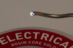
Flux is a reducing agent designed to help reduce (return oxidized metals to their metallic state) metal oxides at the points of contact to improve the electrical connection and mechanical strength. The two principal types of flux are acid flux (sometimes called "active flux"), containing strong acids, used for metal mending and plumbing, and rosin flux (sometimes called "passive flux"), used in electronics. Rosin flux comes in a variety of "activities", corresponding roughly to the speed and effectiveness of the organic acid components of the rosin in dissolving metallic surface oxides, and consequently the corrosiveness of the flux residue.
Due to concerns over atmospheric pollution and hazardous waste disposal, the electronics industry has been gradually shifting from rosin flux to water-soluble flux, which can be removed with deionized water and detergent, instead of hydrocarbon solvents. Water-soluble fluxes are generally more conductive than traditionally used electrical / electronic fluxes and so have more potential for electrically interacting with a circuit; in general it is important to remove their traces after soldering. Some rosin type flux traces likewise should be removed, and for the same reason.
In contrast to using traditional bars or coiled wires of all-metal solder and manually applying flux to the parts being joined, much hand soldering since the mid-20th century has used flux-core solder. This is manufactured as a coiled wire of solder, with one or more continuous bodies of inorganic acid or rosin flux embedded lengthwise inside it. As the solder melts onto the joint, it frees the flux and releases that on it as well.
Operation
The solidifying behavior depends on the alloy composition. Pure metals solidify at a certain temperature, forming crystals of one phase. Eutectic alloys also solidify at a single temperature, all components precipitating simultaneously in so-called coupled growth. Non-eutectic compositions on cooling start to first precipitate the non-eutectic phase; dendrites when it is a metal, large crystals when it is an intermetallic compound. Such a mixture of solid particles in a molten eutectic is referred to as a mushy state. Even a relatively small proportion of solids in the liquid can dramatically lower its fluidity.[28]
The temperature of total solidification is the solidus of the alloy, the temperature at which all components are molten is the liquidus.
The mushy state is desired where a degree of plasticity is beneficial for creating the joint, allowing filling larger gaps or being wiped over the joint (e.g. when soldering pipes). In hand soldering of electronics it may be detrimental as the joint may appear solidified while it is not yet. Premature handling of such joint then disrupts its internal structure and leads to compromised mechanical integrity.
Intermetallics
Many different intermetallic compounds are formed during solidifying of solders and during their reactions with the soldered surfaces.[25] The intermetallics form distinct phases, usually as inclusions in a ductile solid solution matrix, but also can form the matrix itself with metal inclusions or form crystalline matter with different intermetallics. Intermetallics are often hard and brittle. Finely distributed intermetallics in a ductile matrix yield a hard alloy while coarse structure gives a softer alloy. A range of intermetallics often forms between the metal and the solder, with increasing proportion of the metal; e.g. forming a structure of Cu–Cu
3Sn–Cu
6Sn
5–Sn. Layers of intermetallics can form between the solder and the soldered material. These layers may cause mechanical reliability weakening and brittleness, increased electrical resistance, or electromigration and formation of voids. The gold-tin intermetallics layer is responsible for poor mechanical reliability of tin-soldered gold-plated surfaces where the gold plating did not completely dissolve in the solder.
Two processes play a role in a solder joint formation: interaction between the substrate and molten solder, and solid-state growth of intermetallic compounds. The base metal dissolves in the molten solder in an amount depending on its solubility in the solder. The active constituent of the solder reacts with the base metal with a rate dependent on the solubility of the active constituents in the base metal. The solid-state reactions are more complex – the formation of intermetallics can be inhibited by changing the composition of the base metal or the solder alloy, or by using a suitable barrier layer to inhibit diffusion of the metals.[29]
Some example interactions include:
- Gold and palladium readily dissolve in solders. Copper and nickel tend to form intermetallic layers during normal soldering profiles. Indium forms intermetallics as well.
- Indium-gold intermetallics are brittle and occupy about 4 times more volume than the original gold. Bonding wires are especially susceptible to indium attack. Such intermetallic growth, together with thermal cycling, can lead to failure of the bonding wires.[30]
- Copper plated with nickel and gold is often used. The thin gold layer facilitates good solderability of nickel as it protects the nickel from oxidation; the layer has to be thin enough to rapidly and completely dissolve so bare nickel is exposed to the solder.[16]
- Lead-tin solder layers on copper leads can form copper-tin intermetallic layers; the solder alloy is then locally depleted of tin and form a lead-rich layer. The Sn-Cu intermetallics then can get exposed to oxidation, resulting in impaired solderability.[31]
- Cu
6Sn
5 – common on solder-copper interface, forms preferentially when excess of tin is available; in presence of nickel, (Cu,Ni)
6Sn
5 compound can be formed[19][6] - Cu
3Sn – common on solder-copper interface, forms preferentially when excess of copper is available, more thermally stable than Cu
6Sn
5, often present when higher-temperature soldering occurred[19][6] - Ni
3Sn
4 – common on solder-nickel interface[19][6] - FeSn
2 – very slow formation - Ag
3Sn - at higher concentration of silver (over 3%) in tin forms platelets that can serve as crack initiation sites. - AuSn
4 – β-phase – brittle, forms at excess of tin. Detrimental to properties of tin-based solders to gold-plated layers. - AuIn
2 – forms on the boundary between gold and indium-lead solder, acts as a barrier against further dissolution of gold
| Tin | Lead | Indium | |
|---|---|---|---|
| Copper | Cu 4Sn, Cu 6Sn 5, Cu 3Sn, Cu 3Sn 8[19] |
Cu 3In, Cu 9In 4 | |
| Nickel | Ni 3Sn, Ni 3Sn 2, Ni 3Sn 4 NiSn 3 |
Ni 3In, NiIn Ni 2In 3, Ni 3In 7 | |
| Iron | FeSn, FeSn 2 |
||
| Indium | In 3Sn, InSn 4 |
In 3Pb |
– |
| Antimony | SbSn | ||
| Bismuth | BiPb 3 |
||
| Silver | Ag 6Sn, Ag 3Sn |
Ag 3In, AgIn 2 | |
| Gold | Au 5Sn, AuSn AuSn 2, AuSn 4 |
Au 2Pb, AuPb 2 |
AuIn, AuIn 2 |
| Palladium | Pd 3Sn, Pd 2Sn, Pd 3Sn 2, PdSn, PdSn 2, PdSn 4 |
Pd 3In, Pd 2In, PdIn, Pd 2In 3 | |
| Platinum | Pt 3Sn, Pt 2Sn, PtSn, Pt 2Sn 3, PtSn 2, PtSn 4 |
Pt 3Pb, PtPb PtPb 4 |
Pt 2In 3, PtIn 2, Pt 3In 7 |
Preform
A preform is a pre-made shape of solder specially designed for the application where it is to be used. Many methods are used to manufacture the solder preform, stamping being the most common. The solder preform may include the solder flux needed for the soldering process. This can be an internal flux, inside the solder preform, or external, with the solder preform coated.
Similar substances
Glass solder is used to join glasses to other glasses, ceramics, metals, semiconductors, mica, and other materials, in a process called glass frit bonding. The glass solder has to flow and wet the soldered surfaces well below the temperature where deformation or degradation of either of the joined materials or nearby structures (e.g., metallization layers on chips or ceramic substrates) occurs. The usual temperature of achieving flowing and wetting is between 450 and 550 °C (840 and 1,020 °F).
See also
- Body solder
- Graping
- Restriction of Hazardous Substances Directive
- Solderability
- Solder alloys
- Solder mask
- Solder fatigue
- Wood's metal
- Solder paste
References
- ↑ "solder". solder. Oxford University Press. http://www.lexico.com/definition/solder.
- ↑ "solder". Oxford American Dictionary. Oxford University Press. 1980.
- ↑ Frank Oberg, Franklin D. Jones, Holbrook L. Horton, Henry H. Ryffel eds. (1988) Machinery's Handbook 23rd Edition Industrial Press Inc., p. 1203. ISBN 0-8311-1200-X
- ↑ Ogunseitan, Oladele A. (2007). "Public health and environmental benefits of adopting lead-free solders". Journal of the Minerals, Metals and Materials Society 59 (7): 12–17. doi:10.1007/s11837-007-0082-8. Bibcode: 2007JOM....59g..12O.
- ↑ Harper, Douglas. "solder". Online Etymology Dictionary. https://www.etymonline.com/?term=solder.
- ↑ 6.0 6.1 6.2 6.3 Nan Jiang (2019). "Reliability issues of lead-free solder joints in electronic devices". Science and Technology of Advanced Materials 20 (1): 876–901. doi:10.1080/14686996.2019.1640072. PMID 31528239. Bibcode: 2019STAdM..20..876J.

- ↑ "Basic Info on Tin Whiskers". http://nepp.nasa.gov/Whisker/background/index.htm.
- ↑ "A New (Better) Approach to Tin Whisker Mitigation". DFR Solutions. http://www.dfrsolutions.com/uploads/white-papers/WP_SnWhisker.pdf.
- ↑ Properties of Solders. farnell.com.
- ↑ "U.S. Code: Title 42. The Public Health and Welfare". govinfo.gov. p. 990. https://www.gpo.gov/fdsys/pkg/USCODE-2010-title42/pdf/USCODE-2010-title42-chap6A-subchapXII.pdf.
- ↑ H.L. Needleman (1990). "The long-term effects of exposure to low doses of lead in childhood. An 11-year follow-up report". The New England Journal of Medicine 322 (2): 83–8. doi:10.1056/NEJM199001113220203. PMID 2294437.
- ↑ Joseph R. Davis (2001). Alloying: understanding the basics. ASM International. p. 538. ISBN 978-0-87170-744-4. https://books.google.com/books?id=Sg9fAVdf8WoC&pg=PA538.
- ↑ 13.0 13.1 13.2 Howard H. Manko (2001). Solders and soldering: materials, design, production, and analysis for reliable bonding. McGraw-Hill Professional. p. 164. ISBN 978-0-07-134417-3. https://books.google.com/books?id=MvSMg5HC1YcC&pg=PA164.
- ↑ A. C. Tan (1989). Lead finishing in semiconductor devices: soldering. World Scientific. p. 45. ISBN 978-9971-5-0679-7. https://books.google.com/books?id=6F3TYrNmbjAC&pg=PA45.
- ↑ Madhav Datta; Tetsuya Ōsaka; Joachim Walter Schultze (2005). Microelectronic packaging. CRC Press. p. 196. ISBN 978-0-415-31190-8. https://books.google.com/books?id=qj6OJ_jTcg8C&pg=PA196.
- ↑ 16.0 16.1 Karl J. Puttlitz; Kathleen A. Stalter (2004). Handbook of lead-free solder technology for microelectronic assemblies. CRC Press. p. 541. ISBN 978-0-8247-4870-8. https://books.google.com/books?id=H75TywRXUK4C&pg=PA541.
- ↑ 17.0 17.1 Sanka Ganesan; Michael Pecht (2006). Lead-free electronics. Wiley. p. 110. ISBN 978-0-471-78617-7. https://books.google.com/books?id=z4Ha0AYdon4C&pg=PA110.
- ↑ Peter Biocca (19 April 2006). "Lead-free Hand-soldering – Ending the Nightmares". https://www.kester.com/Portals/0/Documents/Knowledge%20Base/Lead-free-Handsoldering.Final_.4.19.06.pdf.
- ↑ 19.0 19.1 19.2 19.3 19.4 19.5 19.6 19.7 Meng Zhao, Liang Zhang, Zhi-Quan Liu, Ming-Yue Xiong, and Lei Sun (2019). "Structure and properties of Sn-Cu lead-free solders in electronics packaging". Science and Technology of Advanced Materials 20 (1): 421–444. doi:10.1080/14686996.2019.1591168. PMID 31489052. Bibcode: 2019STAdM..20..421Z.

- ↑ Kaushish (2008). Manufacturing Processes. PHI Learning Pvt. Ltd.. p. 378. ISBN 978-81-203-3352-9. https://books.google.com/books?id=1ZOXXV9LdcwC&pg=PA378.
- ↑ 21.0 21.1 21.2 King-Ning Tu (2007) Solder Joint Technology – Materials, Properties, and Reliability. Springer. ISBN 978-0-387-38892-2
- ↑ "The Fluidity of the Ni-Modified Sn-Cu Eutectic Lead-free Solder". https://www.aimsolder.com/sites/default/files/the_fluidity_of_the_ni-modified_sn-cu_eutectic_lead-free_solder_white_paper.pdf.
- ↑ I. R. Walker (2011). Reliability in Scientific Research: Improving the Dependability of Measurements, Calculations, Equipment, and Software. Cambridge University Press. pp. 160–. ISBN 978-0-521-85770-3. https://books.google.com/books?id=zhX_5hccFWMC&pg=PA160.
- ↑ "Balver Zinn Desoxy RSN". http://www.balverzinn.com/downloads/DESOXY_RSN_GB.pdf.
- ↑ 25.0 25.1 Michael Pecht (1993). Soldering processes and equipment. Wiley-IEEE. p. 18. ISBN 978-0-471-59167-2. https://books.google.com/books?id=Mu0o3X_k7p8C&pg=PA18.
- ↑ "Solder selection for photonic packaging". 2013-02-27. http://www.aimsolder.com/specialty-materials-division-solders-photonic-packing.
- ↑ SN100C® Technical Guide. floridacirtech.com
- ↑ Keith Sweatman & Tetsuro Nishimura (2006). "The Fluidity of the Ni-Modified Sn-Cu Eutectic Lead-Free Solder". http://www.aimsolder.com/sites/default/files/the_fluidity_of_the_ni-modified_sn-cu_eutectic_lead-free_solder_white_paper.pdf.
- ↑ D. R. Frear; Steve Burchett; Harold S. Morgan; John H. Lau (1994). The Mechanics of solder alloy interconnects. Springer. p. 51. ISBN 978-0-442-01505-3. https://books.google.com/books?id=HgqTNwFkfeEC&pg=PA51.
- ↑ Indium Solder Encapsulating Gold Bonding Wire Leads to Fragile Gold-Indium Compounds and an Unreliable Condition that Results in Wire Interconnection Rupture. GSFC NASA Advisory]. (PDF). Retrieved on 2019-03-09.
- ↑ Jennie S. Hwang (1996). Modern solder technology for competitive electronics manufacturing. McGraw-Hill Professional. p. 397. ISBN 978-0-07-031749-9. https://books.google.com/books?id=GTq6w21s2cwC&pg=PA397.
External links
 |
