Engineering:Lockheed Martin X-35
| X-35 JSF | |
|---|---|
| |
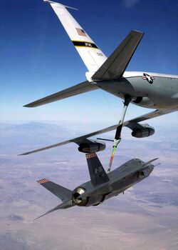
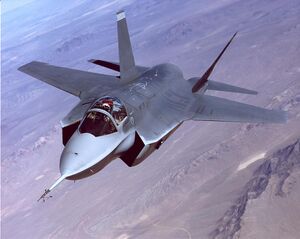
| The X-35A JSF performs flight tests at Edwards Air Force Base, California | |
| Role | Concept demonstrator aircraft (CDA) |
| Manufacturer | Lockheed Martin Aeronautics |
| First flight | 24 October 2000[1][2] |
| Status | Devoloped into the F-35 |
| Primary user | Defense Advanced Research Projects Agency (DARPA) |
| Number built | 2 (X-35A/B and X-35C) |
| Developed into | Lockheed Martin F-35 Lightning II |
The Lockheed Martin X-35 is a concept demonstrator aircraft (CDA) developed by Lockheed Martin for the Joint Strike Fighter program. The X-35 was declared the winner over the competing Boeing X-32 and a developed, armed version went on to enter production in the early 21st century as the F-35 Lightning II.
Development
The Joint Strike Fighter evolved out of several requirements for a common fighter to replace existing types. The actual JSF development contract was signed on 16 November 1996. The JSF program was created to replace various aircraft while keeping development, production, and operating costs down. This was pursued by building three variants of one aircraft, with the initial goal of the variants sharing over 70% of their parts.[3]
The first is the F-35A, a conventional takeoff and landing (CTOL) variant. It is the smallest and lightest version, and is intended primarily to replace the U.S. Air Force's aging F-16 Fighting Falcons and A-10 Thunderbolt IIs. This is the only version with an internal gun, the GAU-22. The F-35B is the short-takeoff and vertical-landing (STOVL) variant due to replace the U.S. Marine Corps AV-8 Harrier IIs and F/A-18 Hornets, and Royal Air Force /Royal Navy Harrier GR7/GR9s beginning in 2015.
The Royal Navy will use this to replace its Harrier GR7s and the RAF replace its Harrier GR9s. The U.S. Marine Corps will use the F-35B to replace both its AV-8B Harrier IIs and F/A-18 Hornets with a design similar in size to the Air Force F-35A, trading fuel volume for vertical flight systems. Like the Harrier, guns will be carried in a pod. Vertical flight is by far the riskiest, and in the end, a decisive factor in design. Lastly, the F-35C, a carrier-based (CV) variant, will replace the "legacy" F/A-18 Hornets and serve as a stealthy complement to the F/A-18E/F Super Hornet.
It will have a larger, folding wing and larger control surfaces for improved low-speed control, and stronger landing gear for the stresses of carrier landings. The larger wing area provides increased range and payload, achieving much the same goal as the much heavier Super Hornet. The U.S. Navy initially planned to purchase 480 JSF; this number was eventually revised to 260 aircraft, with an additional 80 for the U.S. Marine Corps.
The primary customers and financial backers are the United States and the United Kingdom. Eight other nations are also funding the aircraft's development. Total program development costs, less procurement, are estimated at over United States dollar 40 billion, of which the bulk has been underwritten by the United States. Production costs are estimated at United States dollar 102 million per unit for 2,400 units.[4]
There are three levels of international participation. The United Kingdom is the sole 'Level 1' partner, contributing slightly over US$2 billion, about 10% of the development costs. Level 2 partners are Italy, which is contributing US$1 billion, and the Netherlands, US$800 million. At Level 3 are Canada , US$440 million; Turkey, US$175 million; Australia , US$144 million; Norway , US$122 million; and Denmark , US$110 million. The levels generally reflect the financial stake in the program, the amount of technology transfer and subcontracts open for bid by national companies, and the priority order in which countries can obtain production aircraft. Israel and Singapore have also joined as Security Cooperative Participants.[5] Due to delays in development and testing, the introduction date of the F-35 was gradually pushed from 2010 to 2015.[6][7]
Design
File:F-35 compilation.ogg File:F-35 vertical landing.ogg Elements of the X-35 design were pioneered by the F-22 Raptor, and portions of the VTOL exhaust duct design were previously used by the Convair Model 200, a 1972 supersonic VTOL fighter requirement for the Sea Control Ship; in particular, the three-bearing swivel nozzle used in the X-35B was pioneered by the Convair design.[8][9]
Additionally, Lockheed purchased technical data from the canceled Yakovlev Yak-141 in 1991 for examination and analysis of its swivel nozzle.[N 1][11][12][13] Although helmet-mounted display systems have already been integrated into some fourth-generation fighters such as the JAS 39 Gripen, the F-35 will be the first modern combat aircraft in which helmet-mounted displays will replace a head-up display altogether.[14]
During concept definition, two demonstrator airframes for each contractor team would be flight-tested. Lockheed Martin's[N 2] demonstrator aircraft consisted of the X-35A (which was later converted into the X-35B), and the larger-winged X-35C.[15] Both the X-32 and X-35 power plants were derived from Pratt & Whitney's F119, with the STOVL variant of the latter incorporating a Rolls-Royce Lift Fan module. Because these were proof of concept demonstrators for STOVL risk reduction, the demonstrator aircraft did not need to have the internal structure or most subsystems of the final aircraft as a weapon system.[16]
Shaft-driven lift fan
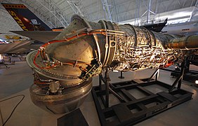
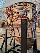
Instead of lift engines or using a direct lift engine like the Rolls-Royce Pegasus in the Harrier jump jet, the X-35B was powered by the F119-PW-611 which used the new shaft-driven lift fan system, patented by Lockheed Martin engineer Paul Bevilaqua, and developed by Rolls-Royce.[17][18] In normal wing-borne flight, the F119-PW-611 was configured as a normal medium-bypass reheated turbofan. The turbofan acted somewhat like a turboshaft engine embedded into the fuselage (but with a much smaller percentage of total heat energy being extracted by the turbine stage).[19]
A portion of engine power was extracted via a turbine, and used to drive a shaft running forward via a clutch-and-bevel gearbox to a vertically mounted, contra-rotating lift fan. This was located forward of the main engine in the center of the aircraft (this can also be viewed the same as a high-bypass turbofan but with the low-pressure fan stages mounted remotely from the engine core on an extended, clutched shaft, and creating thrust downwards rather than back around the engine core as in a conventional turbofan).[20]
Bypass air from the cruise engine medium-bypass turbofan compressor stages exhausted through a pair of roll-post nozzles in the wings on either side of the fuselage, while the thrust from the lift fan balanced the thrust of the hot core stream exhausting through vectored cruise nozzle at the tail. The X-35B powerplant effectively acted as a flow multiplier, much as a turbofan achieves efficiencies by moving unburned air at a lower velocity, and getting the same effect as the Harrier's huge, but supersonically impractical main fan.[21]
Like lift engines, this added machinery was dead weight during flight, but the increased lift thrust enhanced take-off payload by even more. The cool fan also reduced the harmful effects of hot, high-velocity air which could harm runway pavement or an aircraft carrier deck. Though risky and complicated, it was made to work to the satisfaction of DoD officials, and flight testing of the X-35 demonstrators reduced risk to Technology Readiness Level 6.[22]
Operational history
Flight test evaluation
The X-35A first flew on 24 October 2000 and tested air vehicle performance and handling characteristics. After 28 test flights, the aircraft was converted to the X-35B, which added the shaft-drive lift fan, aft swivel nozzle, and roll posts. On 20 July 2001, to demonstrate the X-35's STOVL capability, the X-35B took off in less than 500 feet (150 m), went supersonic, and landed vertically.[23][24][25] The X-35C first flew on 16 December 2000 and tested simulated carrier recovery and power approach.[26]
In the fly-off between the X-32 and the X-35, the latter was judged to be the winner. As a result, a contract for System Development and Demonstration (SDD) of the F-35 was awarded on 26 October 2001 to Lockheed Martin.[27]
F-35 production
There are a number of differences between the X-35 and F-35, which was designed to be an operational weapon system. The forward fuselage was lengthened by 5 inches (13 cm) to make room for mission avionics, while the horizontal stabilizers were correspondingly moved 2 inches (5.1 cm) aft to retain balance and control. The diverterless supersonic inlet cowl shape changed from a four-sided to a three-sided shape and was moved 30 inches (76 cm) aft. To accommodate weapons bays, the fuselage section was fuller with the top surface raised by 1 inch (2.5 cm) along the centerline. Following the designation of the X-35 prototypes, the three variants were designated F-35A (CTOL), F-35B (STOVL), and F-35C (CV).[28]
Aircraft on display
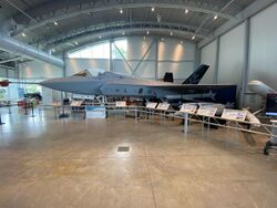
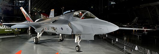
The X-35A was converted into the X-35B for the STOVL part of the competition. It now resides at the National Air and Space Museum Steven F. Udvar-Hazy Center, near Washington Dulles International Airport in Virginia.[29]
Following the end of the competition, the X-35C was transferred to the Patuxent River Naval Air Museum in St. Mary's County, Maryland.[30]
Specifications (X-35A)
Data from Air Force Magazine,[31] Aviation Week & Space Technology,[32][33] Flight International,[34] Aerospace America[35]
General characteristics
- Crew: 1
- Length: 50.5 ft (15.4 m)
- Wingspan: 33 ft (10 m)
- Height: 13.3 ft (4.1 m)
- Wing area: 450 sq ft (42 m2)
- Empty weight: 26,500 lb (12,020 kg)
- Max takeoff weight: 50,000 lb (22,680 kg)
- Fuel capacity: 15,000 lb (6,800 kg) internal
- Powerplant: 1 × Pratt & Whitney JSF119-PW-611 augmented turbofan, 25,000 lbf (110 kN) thrust dry, 40,000 lbf (180 kN) with afterburner
Performance
- Maximum speed: Mach 1.5+ at altitude
- Range: 1,200 nmi (1,400 mi, 2,200 km) or more[N 3]
- Combat range: 600 nmi (690 mi, 1,100 km)
- Service ceiling: 50,000 ft (15,000 m)
Differences between variants
| X-35A CTOL |
X-35B STOVL |
X-35C CV | |
|---|---|---|---|
| Length | 50.5 ft (15.4 m) | 50.5 ft (15.4 m) | 50.8 ft (15.5 m) |
| Wingspan | 33 ft (10.1 m) | 33 ft (10.1 m) | 40 ft (12.2 m) |
| Wing Area | 450 sq ft (41.81 m2) | 450 sq ft (41.81 m2) | 540 sq ft (50.17 m2) |
| Empty weight | 26,500 lb (12,000 kg) | 30,697 lb (13,924 kg) | 30,618 lb (13,888 kg) |
| Internal fuel | 15,000 lb (6,800 kg) | 15,000 lb (6,800 kg) | 16,000 lb (7,300 kg) |
| Range | >1,200 nmi (2,200 km) | >1,200 nmi (2,200 km) | >1,400 nmi (2,600 km) |
Gallery
See also
- Future Offensive Air System
- Joint Combat Aircraft
Related development
Aircraft of comparable role, configuration and era
Related lists
- List of fighter aircraft
- List of experimental aircraft
- List of military aircraft of the United States
Notes
- ↑ The X-35B and Yak-141 have design similarities in their swivel nozzles, but the STOVL propulsion cycles are distinct, with the X-35B using a shaft-driven lift fan for vertical lift augmentation while the Yak-141 uses two dedicated lift engines.[10]
- ↑ Lockheed acquired General Dynamics fighter division at Fort Worth in 1993 and merged with Martin Marietta in 1995 to form Lockheed Martin.
- ↑ The X-35C was stated to have over 100 nmi of additional range over the X-35A.
References
- ↑ "JSF History." JSF. Retrieved 11 January 2011.
- ↑ https://www.af.mil/News/Photos/igphoto/2000416474/
- ↑ Tirpak, John (14 March 2016). "All For One and One for All". Air Force Mag. https://www.airforcemag.com/all-for-one-and-all-for-all/.
- ↑ Merle, Renae. "GAO Questions Cost of Joint Strike Fighter." Washington Post, 16 March 2005. Retrieved: 9 January 2010.
- ↑ Schnasi, Katherine V. "Joint Strike Fighter Acquisition: Observations on the Supplier Base." US Accounts Office. Retrieved 8 February 2006.
- ↑ Charette, Robert (12 September 2012). "F-35 Program Continues to Struggle with Software". IEEE Spectrum. https://spectrum.ieee.org/riskfactor/aerospace/military/f35-program-continues-to-struggle-with-software.
- ↑ "FY18 DOD PROGRAMS F-35 Joint Strike Fighter (JSF)". 2018. p. 25. http://www.dote.osd.mil/pub/reports/FY2018/pdf/dod/2018f35jsf.pdf.
- ↑ "Vertiflight". Journal of the American Helicopter Society, January 2004.
- ↑ Bradley, Robert (2013). Convair Advanced Designs II. Manchester, UK: Crécy Publishing. ISBN 978-0-8597917-0-0.
- ↑ Renshaw, Kevin (12 August 2014). "F-35B Lightning II Three-Bearing Swivel Nozzle". Code One Magazine. https://www.codeonemagazine.com/f35_article.html?item_id=137.
- ↑ Jackson 2000, p. 700.
- ↑ "Joint Strike Fighter (JSF)." Jane’s. Retrieved 9 January 2010.
- ↑ Gunston, William 'Bill'; Gordon, Yefim (1997). Yakovlev Aircraft since 1924. London, UK: Putnam Aeronautical Books. ISBN 978-1-55750-978-9.
- ↑ Jenkins, Jim. "Chief test pilot gives brief on F-35." DC military, 2001. Retrieved 6 July 2008.
- ↑ "History." Joint Strike Fighter (official site). Retrieved 9 January 2010.
- ↑ "Rolls-Royce LiftSystem demonstrates success in first vertical landing." Rolls-Royce, 19 March 2010. Retrieved 14 April 2012.
- ↑ Bevilaqua, Paul M; Shumpert, Paul K, Propulsion system for a vertical and short takeoff and landing aircraft, United States: Patent genius, 5209428, http://www.patentgenius.com/patent/5209428.html, retrieved 9 January 2010.
- ↑ Smith, John and John Kent. "Design News magazine's Engineer of the Year award goes to lift fan inventor at Lockheed Martin." Lockheed Martin, 26 February 2004. Retrieved 9 January 2010.
- ↑ Bevilaqua, p. 779
- ↑ Bevilaqua, p. 779
- ↑ Bevilaqua, pp. 780–782
- ↑ Bevilaqua, pp. 782–783
- ↑ "X-planes". Nova transcript. PBS. Retrieved 9 January 2010.
- ↑ "Propulsion system in Lockheed Martin Joint Strike Fighter wins Collier Trophy." Lockheed Martin, 28 February 2003. Retrieved 9 January 2010.
- ↑ "Lockheed Martin Makes Aviation History With Joint Strike Fighter". Flight International. https://www.flightglobal.com/pdfarchive/view/2001/2001%20-%202838.html?search=X-35B.
- ↑ Warwick, Graham (June 2001). "Testing Time". Flight International: 70–72. https://www.flightglobal.com/pdfarchive/view/2001/2001%20-%202278.html?search=X-35B.
- ↑ Bolkcom, Christopher. "JSF: Background, Status, and Issues," p. CRS-4. DTIC, 16 June 2003. Retrieved 18 September 2010.
- ↑ Hehs, Eric (15 May 2008). "X to F: F-35 Lightning II And Its X-35 Predecessors". Lockheed Martin. http://www.codeonemagazine.com/f35_article.html?item_id=28.
- ↑ "X-35B." National Air and Space Museum. Retrieved: 18 June 2021.
- ↑ "Exhibits". Patuxent River Naval Air Museum. 18 June 2021. https://paxmuseum.com/exhibits/.
- ↑ Tirpak, John (October 1998). "Scoping Out the New Strike Fighter". Air Force Magazine: 36–41.
- ↑ Wall, Robert; Fulghum, David (1 February 1999). "Lockheed Martin Sets JSF Design, Turns to Cost, Subsystem Work". Aviation Week. https://aviationweek.com/lockheed-martin-sets-jsf-design-turns-cost-subsystem-work.
- ↑ Fulghum, David (5 March 2001). "Navy X-35C JSF Demonstrator Lands Slower, Flies Farther". Aviation Week. https://aviationweek.com/navy-x-35c-jsf-demonstrator-lands-slower-flies-farther.
- ↑ Warwick, Graham (5 March 2001). "Hover pit testing begins for X-35C Joint Strike Fighter". Flight International. https://www.flightglobal.com/hover-pit-testing-begins-for-x-35c-joint-strike-fighter/36433.article.
- ↑ Iannotta, Ben (January 2001). "JSF Rivals Face Off". Aerospace America: 34–40.
Bibliography
- Bevilaqua, Paul M. (September 2005). "Joint Strike Fighter Dual-Cycle Propulsion System". Journal of Propulsion and Power 21 (5): 778–783. doi:10.2514/1.15228. https://arc.aiaa.org/doi/abs/10.2514/1.15228.
- Eden, Paul, ed (2004). The Encyclopedia of Modern Military Aircraft. London, UK: Amber Books. ISBN 1-904687-84-9.
- Hamstra, Jeffrey (2019). Hamstra, Jeffrey W. ed. The F-35 Lightning II: From Concept to Cockpit. American Institute of Aeronautics and Astronautics (AIAA). doi:10.2514/4.105678. ISBN 978-1-62410-566-1. https://arc.aiaa.org/doi/book/10.2514/4.105678.
- Jackson, Paul, ed. (2000), All the World's Aircraft: 2000–2001, Coulsdon, Surrey, UK: Jane's Information Group, ISBN 0-7106-2011-X.
- Jenkins, Dennis R; Landis, Tony R (2008), Experimental & Prototype US Air Force Jet Fighters, Minnesota, US: Specialty Press, ISBN 978-1-58007-111-6.
- Keijsper, Gerald (2007), Lockheed F-35 Joint Strike Fighter, London: Pen & Sword Aviation, ISBN 978-1-84415-631-3.
- Spick, Michael 'Mike' (2002), The Illustrated Directory of Fighters, New York: Salamander Books, ISBN 1-84065-384-1.
External links
- "Battle of the X-Planes (JSF selection)", Nova, PBS, https://www.pbs.org/wgbh/nova/xplanes/.
- F-35 JSF news articles, F-16, http://www.f-16.net/f-16_news_topic19.html.
- Gallery, LMTAS, http://www.lmtas.com/gallery/products/combat_air/x35/.
- "program difficulties", The Australian (News), 28 June 2006, http://www.theaustralian.news.com.au/common/story_page/0,5744,9428149%5e421,00.html.
- F-35 Joint Strike Fighter (JSF), The Federation of American Scientists, http://www.fas.org/man/dod-101/sys/ac/f-35.htm.
 |
