Engineering:Rocketdyne J-2
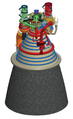
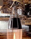
 J-2 test firing | |
| Country of origin | United States |
|---|---|
| First flight | 26 February 1966 (AS-201) |
| Last flight | 15 July 1975 (ASTP) |
| Designer | Marshall Space Flight Center · Rocketdyne |
| Manufacturer | Rocketdyne |
| Application | Upper stage engine |
| Associated L/V | Saturn IB · Saturn V |
| Successor | HG-3 J-2X |
| Status | Retired |
| Liquid-fuel engine | |
| Propellant | Liquid oxygen / Liquid hydrogen |
| Mixture ratio | 5.5:1 |
| Cycle | Gas generator |
| Configuration | |
| Nozzle ratio | 27.5:1 |
| Performance | |
| Thrust (vac.) | 1,033.1 kN (232,250 lbf) |
| Thrust (SL) | 486.2 kN (109,302 lbf) |
| Thrust-to-weight ratio | 73.18:1 |
| Chamber pressure | 5,260 kPa (763 psi) |
| Isp (vac.) | 421 s (4.13 km/s) |
| Isp (SL) | 200 s (2.0 km/s) |
| Burn time | 500 seconds |
| Dimensions | |
| Length | 3.4 m (11.1 ft) |
| Diameter | 2.1 m (6.8 ft) |
| Dry weight | 1,788.1 kg (3,942 lb) |
| Used in | |
| S-IVB · S-II | |
| References | |
| References | [1][2][3] |
| Notes | Data is for SA-208/SA-504 version. |
The J-2, commonly known as Rocketdyne J-2, was a liquid-fuel cryogenic rocket engine used on NASA's Saturn IB and Saturn V launch vehicles. Built in the United States by Rocketdyne, the J-2 burned cryogenic liquid hydrogen (LH2) and liquid oxygen (LOX) propellants, with each engine producing 1,033.1 kN (232,250 lbf) of thrust in vacuum. The engine's preliminary design dates back to recommendations of the 1959 Silverstein Committee. Rocketdyne won approval to develop the J-2 in June 1960 and the first flight, AS-201, occurred on 26 February 1966. The J-2 underwent several minor upgrades over its operational history to improve the engine's performance, with two major upgrade programs, the de Laval nozzle-type J-2S and aerospike-type J-2T, which were cancelled after the conclusion of the Apollo program.
The engine produced a specific impulse (Isp) of 421 seconds (4.13 km/s) in a vacuum (or 200 seconds (2.0 km/s) at sea level) and had a mass of approximately 1,788 kilograms (3,942 lb). Five J-2 engines were used on the Saturn V's S-II second stage, and one J-2 was used on the S-IVB upper stage used on both the Saturn IB and Saturn V. Proposals also existed to use various numbers of J-2 engines in the upper stages of an even larger rocket, the planned Nova. The J-2 was America's largest production LH2-fuelled rocket engine before the RS-25. A modernized version of the engine, the J-2X, was considered for use on the Earth Departure Stage of NASA's Space Shuttle replacement, the Space Launch System.
Unlike most liquid-fueled rocket engines in service at the time, the J-2 was designed to be restarted once after shutdown when flown on the Saturn V S-IVB third stage. The first burn, lasting about two minutes, placed the Apollo spacecraft into a low Earth parking orbit. After the crew verified that the spacecraft was operating nominally, the J-2 was re-ignited for translunar injection, a 6.5 minute burn which accelerated the vehicle to a course for the Moon.
Components

Thrust chamber and gimbal system
The J-2's thrust chamber assembly served as a mount for all engine components, and was composed of the thrust chamber body, injector and dome assembly, gimbal bearing assembly, and augmented spark igniter.[2]
The thrust chamber was constructed of 0.30 millimetres (0.012 in) thick stainless steel tubes, stacked longitudinally and furnace-brazed to form a single unit. The chamber was bell-shaped with a 27.5:1 expansion area ratio for efficient operation at altitude, and was regeneratively cooled by the fuel. Fuel entered from a manifold, located midway between the thrust chamber throat and the exit, at a pressure of more than 6,900 kPa (1,000 psi). In cooling the chamber, the fuel made a one-half pass downward through 180 tubes and was returned in a full pass up to the thrust chamber injector through 360 tubes. Once propellants passed through the injector, they were ignited by the augmented spark igniter and burned to impart a high velocity to the expelled combustion gases to produce thrust.[2]
The thrust chamber injector received the propellants under pressure from the turbopumps, then mixed them in a manner that produced the most efficient combustion. 614 hollow oxidizer posts were machined to form an integral part of the injector, with fuel nozzles (each swaged to the face of the injector) threaded through and installed over the oxidizer posts in concentric rings. The injector face was porous, being formed from layers of stainless steel wire mesh, and was welded at its periphery to the injector body. The injector received LOX through the dome manifold and injected it through the oxidizer posts into the combustion area of the thrust chamber, while fuel was received from the upper fuel manifold in the thrust chamber and injected through the fuel orifices which were concentric with the oxidizer orifices. The propellants were injected uniformly to ensure satisfactory combustion. The injector and oxidizer dome assembly was located at the top of the thrust chamber. The dome provided a manifold for the distribution of the LOX to the injector and served as a mount for the gimbal bearing and the augmented spark igniter.[2]
The augmented spark igniter (ASI) was mounted to the injector face and provided the flame to ignite the propellants in the combustion chamber. When engine start was initiated, the control system started the initial flow of oxidizer and fuel to the spark igniter. Simultaneously, the spark exciters energized two spark plugs mounted in the side of the ASI combustion chamber. As the oxidizer and fuel entered the combustion chamber of the ASI, they mixed and were ignited, with proper ignition being monitored by an ignition monitor mounted in the ASI. The ASI operated continuously during entire engine firing, was uncooled, and was capable of multiple re-ignitions under all environmental conditions.[2] On Apollo 6, the hydrogen line to one of the J-2 engines' ASI broke, initiating a chain of events that shut down two of the five S-II engines prematurely. [4]: p.6-1 [5]
Thrust was transmitted through the gimbal (mounted to the injector and oxidizer dome assembly and the vehicle's thrust structure), which consisted of a compact, highly loaded (140,000 kPa) universal joint consisting of a spherical, socket-type bearing. This was covered with a Teflon/fiberglass coating that provided a dry, low-friction bearing surface. The gimbal included a lateral adjustment device for aligning the combustion chamber with the vehicle, so that, in addition to transmitting the thrust from the injector assembly to the vehicle thrust structure, the gimbal also provided a pivot bearing for deflection of the thrust vector, thus providing flight attitude control of the vehicle.[2]
Propellant feed system
The propellant feed system consists of separate fuel and oxidizer turbopumps (the bearings of which were lubricated by the fluid being pumped because the extremely low operating temperature of the engine precluded use of lubricants or other fluids), several valves (including the main fuel valve, main oxidizer valve, propellant utilization valve and fuel and oxidizer bleed valves), fuel and oxidizer flowmeters, and interconnecting lines.[2]
Fuel turbopump
The fuel turbopump, mounted on the thrust chamber, was a turbine-driven, axial flow pumping unit consisting of an inducer, a seven-stage rotor, and a stator assembly. It was a high-speed pump operating at 27,000 rpm, and was designed to increase hydrogen pressure from 210 to 8,450 kPa (30 to 1,225 psi) (absolute) through high-pressure ducting at a flowrate which develops 5,800 kW (7,800 bhp). Power for operating the turbopump was provided by a high-speed, two-stage turbine. Hot gas from the gas generator was routed to the turbine inlet manifold which distributed the gas to the inlet nozzles where it was expanded and directed at a high velocity into the first stage turbine wheel. After passing through the first stage turbine wheel, the gas was redirected through a ring of stator blades and enters the second stage turbine wheel. The gas left the turbine through the exhaust ducting. Three dynamic seals in series prevented the pump fluid and turbine gas from mixing. Power from the turbine was transmitted to the pump by means of a one-piece shaft.[2]
Oxidizer turbopump
The oxidizer turbopump was mounted on the thrust chamber diametrically opposite the fuel turbopump. It was a single-stage centrifugal pump with direct turbine drive. The oxidizer turbopump increases the pressure of the LOX and pumps it through high-pressure ducts to the thrust chamber. The pump operated at 8,600 rpm at a discharge pressure of 7,400 kPa (1,080 psi) (absolute) and developed 1,600 kW (2,200 bhp). The pump and its two turbine wheels are mounted on a common shaft. Power for operating the oxidizer turbopump was provided by a high-speed, two-stage turbine which was driven by the exhaust gases from the gas generator. The turbines of the oxidizer and fuel turbopumps were connected in a series by exhaust ducting that directed the discharged exhaust gas from the fuel turbopump turbine to the inlet of the oxidizer turbopump turbine manifold. One static and two dynamic seals in series prevented the turbopump oxidizer fluid and turbine gas from mixing.[2]
Beginning the turbopump operation, hot gas entered the nozzles and, in turn, the first stage turbine wheel. After passing through the first stage turbine wheel, the gas was redirected by the stator blades and entered the second stage turbine wheel. The gas then left the turbine through exhaust ducting, passed through the heat exchanger, and exhausted into the thrust chamber through a manifold directly above the fuel inlet manifold. Power from the turbine was transmitted by means of a one-piece shaft to the pump. The velocity of the LOX was increased through the inducer and impeller. As the LOX entered the outlet volute, velocity was converted to pressure and the LOX was discharged into the outlet duct at high pressure.[2]
Fuel and oxidizer flowmeters
The fuel and oxidizer flowmeters were helical-vaned, rotor-type flowmeters. They were located in the fuel and oxidizer high-pressure ducts. The flowmeters measured propellant flowrates in the high-pressure propellant ducts. The four-vane rotor in the hydrogen system produced four electrical impulses per revolution and turned approximately 3,700 rpm at nominal flow. The six-vane rotor in the LOX system produced six electrical impulses per revolution and turned at approximately 2,600 rpm at nominal flow.[2]
Valves
The propellant feed system required a number of valves to control the operation of the engine by changing the flow of propellant through the engine's components:[2]
- The main fuel valve was a butterfly-type valve, spring-loaded to the closed position, pneumatically operated to the open position, and pneumatically assisted to the closed position. It was mounted between the fuel high-pressure duct from the fuel turbopump and the fuel inlet manifold of the thrust chamber assembly. The main fuel valve controlled the flow of fuel to the thrust chamber. Pressure from the ignition stage control valve on the pneumatic control package opened the valve during engine start and, as the gate started to open, it allowed fuel to flow to the fuel inlet manifold.[2]
- The main oxidizer valve (MOV) was a butterfly-type valve, spring-loaded to the closed position, pneumatically operated to the open position, and pneumatically assisted to the closed position. It was mounted between the oxidizer high-pressure duct from the oxidizer turbopump and the oxidizer inlet on the thrust chamber assembly. Pneumatic pressure from the normally closed port of the mainstage control solenoid valve was routed to both the first and second stage opening actuators of the main oxidizer valve. Application of opening pressure in this manner, together with controlled venting of the main oxidizer valve closing pressure through a thermal-compensating orifice, provided a controlled ramp opening of the main oxidizer valve through all temperature ranges. A sequence valve, located within the MOV assembly, supplied pneumatic pressure to the opening control part of the gas generator control valve and through an orifice to the closing part of the oxidizer turbine bypass valve.[2]
- The propellant utilization (PU) valve was an electrically operated, two-phase, motor-driven, oxidizer transfer valve and is located at the oxidizer turbopump outlet volute. The propellant utilization valve ensured the simultaneous exhaustion of the contents of the propellant tanks. During engine operation, propellant level sensing devices in the vehicle propellant tanks controlled the valve gate position for adjusting the oxidizer flow to ensure simultaneous exhaustion of fuel and oxidizer.[2]
- An additional function of the PU Valve was to provide thrust variations in order to maximize payload. The second stage, for example, operated with the PU valve in the closed position for more than 70% of the firing duration. This valve position provided 1,000 kN (225,000 lbf) of thrust at a 5.5:1 propellant (oxidizer to fuel by weight) mixture ratio (when the PU valve was fully open, the mixture ratio was 4.5:1 and the thrust level was 780 kN (175,000 lbf)), though with a higher specific impulse due to more unburned hydrogen in the exhaust. During the latter portion of the flight, the PU valve position was varied to provide simultaneous emptying of the propellant tanks. The third stage also operated at the high-thrust level for the majority of the burning time in order to realize the high thrust benefits. The exact period of time at which the engine operated with the PU valve closed varied with individual mission requirements and propellant tanking levels.[2]
- The propellant bleed valves used in both the fuel and oxidizer systems were poppet-type, which were spring-loaded to the normally open position and pressure-actuated to the closed position. Both propellant bleed valves were mounted to the bootstrap lines adjacent to their respective turbopump discharge flanges. The valves allowed propellant to circulate in the propellant feed system lines to achieve proper operating temperature prior to engine start, and were engine controlled. At engine start, a helium control solenoid valve in the pneumatic control package was energized allowing pneumatic pressure to close the bleed valves, which remained closed during engine operation.[2]
Gas generator and exhaust system
The gas generator system consisted of the gas generator, gas generator control valve, turbine exhaust system and exhaust manifold, heat exchanger, and oxidizer turbine bypass valve.[2]
Gas generator
The gas generator itself was welded to the fuel pump turbine manifold, making it an integral part of the fuel turbopump assembly. It produced hot gases to drive the fuel and oxidizer turbines and consisted of a combustor containing two spark plugs, a control valve containing fuel and oxidizer ports, and an injector assembly. When engine start was initiated, the spark exciters in the electrical control package were energized, providing energy to the spark plugs in the gas generator combustor. Propellants flowed through the control valve to the injector assembly and into the combustor outlet, before being directed to the fuel turbine and then to the oxidizer turbine.[2]
Valves
- The gas generator control valve was a pneumatically operated poppet-type that was spring-loaded to the closed position. The fuel and oxidizer poppets were mechanically linked by an actuator. The valve controlled the flow of propellants through the gas generator injector. When the mainstage signal was received, pneumatic pressure was applied against the gas generator control valve actuator assembly which moved the piston and opened the fuel poppet. During the fuel poppet opening, an actuator contacted the piston that opened the oxidizer poppet. As the opening pneumatic pressure decayed, spring loads closed the poppets.[2]
- The oxidizer turbine bypass valve was a normally open, spring-loaded, gate type valve. It was mounted in the oxidizer turbine bypass duct and equipped with a nozzle, the size of which was determined during engine calibration. The valve in its open position depressed the speed of the oxygen pump during start, and in its closed position acted as a calibration device for the turbopump performance balance.[2]
Turbine exhaust system
The turbine exhaust ducting and turbine exhaust hoods were of welded sheet metal construction. Flanges utilizing dual seals were used at component connections. The exhaust ducting conducted turbine exhaust gases to the thrust chamber exhaust manifold which encircled the combustion chamber approximately halfway between the throat and the nozzle exit. Exhaust gases passed through the heat exchanger and exhaust into the main combustion chamber through 180 triangular openings between the tubes of the combustion chamber.[2]
Heat exchanger
The heat exchanger was a shell assembly, consisting of a duct, bellows, flanges, and coils. It was mounted in the turbine exhaust duct between the oxidizer turbine discharge manifold and the thrust chamber. It heated and expanded helium gas for use in the third stage or converted LOX to gaseous oxygen for the second stage for maintaining vehicle oxidizer tank pressurization. During engine operation, either LOX was tapped off the oxidizer high-pressure duct or helium was provided from the vehicle stage and routed to the heat exchanger coils.[2]
Start tank assembly system
This system was made up of an integral helium and hydrogen start tank, which contained the hydrogen and helium gases for starting and operating the engine. The gaseous hydrogen imparted initial spin to the turbines and pumps prior to gas generator combustion, and the helium was used in the control system to sequence the engine valves. The spherical helium tank was positioned inside the hydrogen tank to minimize engine complexity. It held 16,000 cm3 (1,000 cu in) of helium. The larger spherical hydrogen gas tank had a capacity of 118,931 cm3 (7,257.6 cu in). Both tanks were filled from a ground source prior to launch and the gaseous hydrogen tank was refilled during engine operation from the thrust chamber fuel inlet manifold for subsequent restart in third stage application.[2]
Control system
The control system included a pneumatic system and a solid-state electrical sequence controller packaged with spark exciters for the gas generator and the thrust chamber spark plugs, plus interconnecting electrical cabling and pneumatic lines, in addition to the flight instrumentation system. The pneumatic system consisted of a high-pressure helium gas storage tank, a regulator to reduce the pressure to a usable level, and electrical solenoid control valves to direct the central gas to the various pneumatically controlled valves. The electrical sequence controller was a completely self-contained, solid-state system, requiring only DC power and start and stop command signals. Pre-start status of all critical engine control functions was monitored in order to provide an "engine ready" signal. Upon obtaining "engine ready" and "start" signals, solenoid control valves were energized in a precisely timed sequence to bring the engine through ignition, transition, and into main-stage operation. After shutdown, the system automatically reset for a subsequent restart.[2]
Flight instrumentation system
The flight instrumentation system was composed of a primary instrumentation package and an auxiliary package. The primary package instrumentation measures those parameters critical to all engine static firings and subsequent vehicle launches. These include some 70 parameters such as pressures, temperatures, flows, speeds, and valve positions for the engine components, with the capability of transmitting signals to a ground recording system or a telemetry system, or both. The instrumentation system was designed for use throughout the life of the engine, from the first static acceptance firing to its ultimate vehicle flight. The auxiliary package was designed for use during early vehicle flights. It may be deleted from the basic engine instrumentation system after the propulsion system has established its reliability during research and development vehicle flights. It contains sufficient flexibility to provide for deletion, substitution, or addition of parameters deemed necessary as a result of additional testing. Eventual deletion of the auxiliary package will not interfere with the measurement capability of the primary package.[2]
Engine operation

Start sequence
Start sequence was initiated by supplying energy to two spark plugs in the gas generator and two in the augmented spark igniter for ignition of the propellants. Next, two solenoid valves were actuated; one for helium control, and one for ignition phase control. Helium was routed to hold the propellant bleed valves closed and to purge the thrust chamber LOX dome, the LOX pump intermediate seal, and the gas generator oxidizer passage. In addition, the main fuel and ASI oxidizer valves were opened, creating an ignition flame in the ASI chamber that passed through the center of the thrust chamber injector.[2]
After a delay of 1, 3, or 8 seconds, during which time fuel was circulated through the thrust chamber to condition the engine for start, the start tank discharge valve was opened to initiate turbine spin. The length of the fuel lead was dependent upon the length of the Saturn V first stage boost phase. When the engine was used in the S-II stage, a 1-second fuel lead was necessary. The S-IVB, on the other hand, utilized a 1-second fuel lead for its initial start and an 8-second fuel lead for its restart.[2]
After an interval of 0.450 seconds, the start tank discharge valve was closed and a mainstage control solenoid was actuated to:[2]
- Turn off gas generator and thrust chamber helium purges
- Open the gas generator control valve (hot gases from the gas generator now drive the pump turbines)
- Open the main oxidizer valve to the first position (14 degrees) allowing LOX to flow to the LOX dome to burn with the fuel that has been circulating through the injector
- Close the oxidizer turbine bypass valve (a portion of the gases for driving the oxidizer turbopump were bypassed during the ignition phase)
- Gradually bleed the pressure from the closing side of the oxidizer valve pneumatic actuator controlling the slow opening of this valve for smooth transition into mainstage.
Energy in the spark plugs was cut off and the engine was operating at rated thrust. During the initial phase of engine operation, the gaseous hydrogen start tank would be recharged in those engines having a restart requirement. The hydrogen tank was repressurized by tapping off a controlled mixture of LH2 from the thrust chamber fuel inlet manifold and warmer hydrogen from the thrust chamber fuel injection manifold just before entering the injector.[2]
Flight mainstage operation
During mainstage operation, engine thrust could be varied between 780 and 1,000 kilonewtons (175,000 and 225,000 lbf) by actuating the propellant utilization valve to increase or decrease oxidizer flow. This was beneficial to flight trajectories and for overall mission performance to make greater payloads possible.[2]
Cutoff sequence
When the engine cutoff signal was received by the electrical control package, it de-energized the main-stage and ignition phase solenoid valves and energized the helium control solenoid de-energizer timer. This, in turn, permitted closing pressure to the main fuel, main oxidizer, gas generator control, and augmented spark igniter valves. The oxidizer turbine bypass valve and propellant bleed valves opened and the gas generator and LOX dome purges were initiated.[2]
Engine restart
To provide third stage restart capability for the Saturn V, the J-2 gaseous hydrogen start tank was refilled in 60 seconds during the previous firing after the engine had reached steady-state operation (refill of the gaseous helium tank was not required because the original ground-fill supply was sufficient for three starts). Prior to engine restart, the stage ullage rockets were fired to settle the propellants in the stage propellant tanks, ensuring a liquid head to the turbopump inlets. In addition, the engine propellant bleed valves were opened, the stage recirculation valve was opened, the stage prevalve was closed, and a LOX and LH2 circulation was effected through the engine bleed system for five minutes to condition the engine to the proper temperature to ensure proper engine operation. Engine restart was initiated after the "engine ready" signal was received from the stage. This was similar to the initial "engine ready". The hold time between cutoff and restart was from a minimum of 1.5 hours to a maximum of 6 hours, depending upon the number of Earth orbits required to attain the lunar window for translunar trajectory.[2]
History
Development

Inspiration for the J-2 dates back to various NASA studies conducted in the late 1950s, of LH2-fuelled engines producing thrust of up to 665 kN (149,000 lbf) following the success of the 67 kN (15,000 lbf) RL-10 used on the Atlas-Centaur's Centaur upper stage. As ever-heavier launch vehicles entered consideration, NASA began to look at engines producing thrusts of up to 890 kN (200,000 lbf), with development being officially authorized following the 1959 report of the Saturn Vehicle Evaluation Committee. A source evaluation board was formed to nominate a contractor from five bidding companies, and approval was given on 1 June 1960 for Rocketdyne to begin development of a "high-energy rocket engine, fuelled by LOX and hydrogen, to be known as the J-2". The final contract, awarded in September 1960, was the first to explicitly require the design "insure maximum safety for crewed flight."[6]
Rocketdyne launched the development of the J-2 with an analytical computer model that simulated engine operations and aided in establishing design configurations. The model was supported by a full-sized mockup which was used throughout development to judge the positioning of the engine's components. The first experimental component, the engine's injector, was produced within two months of the contract being awarded, and testing of the engine's components began at Rocketdyne's Santa Susana Field Laboratory in November 1960. Other test facilities, including a vacuum chamber and full-size engine test stand, were used during the development, with the engine's turbopumps entering testing in November 1961, the ignition system in early 1962, and the first prototype engine running a complete 250-second test run in October 1962. In addition to flight hardware, five engine simulators were also used during the development process, assisting in the design of the engine's electrical and mechanical systems. Contracts were signed between NASA and Rocketdyne in the summer of 1962, requiring 55 J-2 engines to be produced to support the final designs for the Saturn rockets, which required five engines for each S-II second stage of the Saturn V and one engine for each S-IVB Saturn IB and Saturn V third stage.[6]
The J-2 entered production in May 1963, with concurrent testing programs continuing to run at Rocketdyne and at MSFC during the manufacturing run. The first production engine, delivered in April 1964, went for static tests on the S-IVB test stage at the Douglas test facility near Sacramento, California and underwent its first full-duration (410 seconds) static test in December 1964. Testing continued until January 1966, with one engine in particular igniting successfully in 30 successive firings, including five tests at full duration of 470 seconds each. The total firing time of 3774 seconds represented a level of accumulated operational time almost eight times greater than the flight requirements. As successful single-engine tests moved toward their completion, integration tests of the propulsion system with the S-IVB accelerated with the availability of more production engines. The first operational flight, AS-201, was scheduled in early 1966 for the Saturn IB using the S-IB first stage and the S-IVB as the second stage.[6]
The first all-up test of a complete S-IVB, including its single J-2, in July 1965 was inconclusive when a component malfunction in one of the pneumatic consoles prematurely ended the test after a successful propellant loading and automatic countdown. Confidence in the design was regained in August, however, when the same stage, S-IVB-201, performed flawlessly on a full-duration firing of 452 seconds, which was the first engine test sequence to be controlled entirely by computers. The J-2 was cleared for flight and, on 26 February 1966, AS-201 went through a flawless launch. In July 1966, NASA confirmed J-2 production contracts through 1968, by which time Rocketdyne agreed to finish deliveries of 155 J-2 engines, with each engine undergoing a flight qualification firing at the Santa Susana Field Laboratory before delivery to NASA. Reliability and development testing continued on the engine, with two uprated versions being used by NASA in the later flights of the Apollo program.[6]
Upgrades
J-2S
An experimental program to improve the performance of the J-2 started in 1964 as the J-2X (not to be confused with a later variant by the same name). The main change to the original J-2 design was a change from the gas generator cycle to a tap-off cycle that supplied hot gas from a tap on the combustion chamber instead of a separate burner. In addition to removing parts from the engine, it also reduced the difficulty of starting up the engine and properly timing various combustors.[7]
Additional changes included a throttling system for wider mission flexibility, which also required a variable mixture system to properly mix the fuel and oxygen for a variety of different operating pressures. It also included a new "Idle Mode" that produced little thrust for on-orbit maneuvering or to settle the fuel tanks on-orbit prior to a burn.
During the experimental program, Rocketdyne also produced a small run of six pre-production models for testing, the J-2S. These were test fired many times between 1965 and 1972, for a total of 30,858 seconds burn time. In 1972 it became clear no follow-on orders for Saturn boosters were coming, and the program shut down. NASA did consider using the J-2S on a number of different missions, including powering the Space Shuttle in a number of early designs as well as on the Comet HLLV.[8][9]
J-2T
While work on the J-2S continued, NASA also funded a design effort to use the J-2S turbomachinery and plumbing to a toroidal combustion chamber with a new aerospike nozzle. This would improve performance even further. Two versions were built, the J-2T-200k that provided 890 kN (200,000 lbf) thrust,[10] allowing it to be "dropped in" to the existing S-II and S-IVB stages, and the J-2T-250k of 1,100 kN (250,000 lbf).[11]
Like the J-2S, work on the J-2T had progressed to a lengthy series of ground-based test runs, but further development ended in the post-Apollo draw-down.
J-2X
What became a different engine with a similar name, called the J-2X,[12][13] was chosen in 2007 for the Project Constellation crewed lunar landing program. A single J-2X engine, generating 1,310 kN (294,000 lbf) of thrust, was to be used to power the Earth Departure Stage (EDS).[14]
NASA began construction of a new test stand for altitude testing of J-2X engines at Stennis Space Center (SSC) on 23 August 2007.[15] Between December 2007 and May 2008, nine tests of heritage J-2 engine components were conducted at SSC in preparation for the design of the J-2X engine.[16]
The new J-2X is designed to be more efficient and simpler to build than its Apollo J-2 predecessor, and cost less than the Space Shuttle Main Engine (SSME).[17] Design differences include the removal of beryllium, modern electronics, a centrifugal turbo pump versus the axial turbo pump of the J-2, a different chamber and nozzle expansion ratios, a channel-walled combustion chamber versus the tube-welded chamber of the J-2, a redesign of all the electronics, supersonic injection and the use of 21st-century joining techniques.[12][13]
On 16 July 2007 NASA officially announced the award to Pratt & Whitney Rocketdyne, Inc. of a $1.2 billion contract "for design, development, testing and evaluation of the J-2X engine" intended to power the upper stages of the Ares I and Ares V launch vehicles.[18] On September 8, 2008, Pratt & Whitney Rocketdyne announced successful testing of the initial J-2X gas generator design.[19] The completion of a second round of successful gas generator tests was announced on 21 September 2010.[20]
Project Constellation was cancelled by President Barack Obama on 11 October 2010,[21] but development of the J-2X has continued for its potential as the second stage engine for the new, heavy-lift Space Launch System. The first hot-fire test of the J-2X was scheduled for late June 2011.[22]
On 9 November 2011 NASA conducted a successful firing of the J-2X engine of 499.97 seconds in duration.[23]
On 27 February 2013 NASA continued testing of the J-2X engine of 550 seconds in duration at NASA's Stennis Space Center.[24]
In later times, however, the planned upper stage engine for what would become the Exploration Upper Stage for the SLS rocket has since been chosen instead as a variant of the RL-10, the RL-10C-3.[25] As a result of this, development of the J-2X has ceased, with the program officially being "idle" since the end of the prototype's testing regime in 2014.[26]
-
 Concept image of the J-2X engine
 -
 Test of the J-2X engine 'workhorse' gas generator
 -
 Cold Flow nozzle testing for the J2X program


Specifications
| J-2[3] | J-2S[7] | J-2X[12] | |
|---|---|---|---|
| Vacuum thrust: | 1,033.1 kN (232,250 lbf) | 1,138.5 kN (255,945 lbf) | 1,310.0 kN (294,500 lbf) |
| Specific impulse (vacuum) -Isp: | 421 seconds (4.13 km/s) | 436 seconds (4.28 km/s) | 448 seconds (4.39 km/s) |
| Burn time: | 475 seconds | 475 seconds | 465 seconds (Ares I, upper stage) |
| Engine weight - dry: | 1,438 kg (3,170 lb) | 1,400 kg (3,090 lb) | 2,472 kg (5,450 lb) |
| Propellants: | LH2 and LOX | LH2 and LOX | LH2 and LOX |
| Mixture ratio: | 5.50 | 5.50 | 5.50 |
| Diameter: | 2.01 m (6.6 ft) | 2.01 m (6.6 ft) | 3.05 m (10.0 ft) |
| Length: | 3.38 m (11.09 ft) | 3.38 m (11.09 ft) | 4.70 m (15.42 ft) |
| Thrust to Weight Ratio: | 73.18 | 85.32 | 55.04 |
| Contractor: | Rocketdyne | Rocketdyne | Rocketdyne |
| Vehicle application: | Saturn V / S-II 2nd stage - 5-engines, Saturn IB and Saturn V / S-IVB upper stage - 1-engine |
Planned replacement for J-2 on Saturn V / S-II 2nd stage / S-IVB upper stage |
Proposed for Ares I upper stage - 1 engine / Ares V upper stage - 1 engine / Space Launch System Advanced Second Stage/EUS - 1 engine |
See also
References
![]() This article incorporates public domain material from websites or documents of the National Aeronautics and Space Administration.
This article incorporates public domain material from websites or documents of the National Aeronautics and Space Administration.
- ↑ Marshall Space Flight Center. "J-2 engine". NASA. http://mix.msfc.nasa.gov/abstracts.php?p=1093.
- ↑ 2.00 2.01 2.02 2.03 2.04 2.05 2.06 2.07 2.08 2.09 2.10 2.11 2.12 2.13 2.14 2.15 2.16 2.17 2.18 2.19 2.20 2.21 2.22 2.23 2.24 2.25 2.26 2.27 2.28 2.29 2.30 2.31 2.32 "J-2 Engine Fact Sheet". Saturn V News Reference. NASA. December 1968. http://www.nasa.gov/centers/marshall/pdf/499245main_J2_Engine_fs.pdf.
- ↑ 3.0 3.1 "J-2". Astronautix. http://www.astronautix.com/j/j-2.html.
- ↑ Cite error: Invalid
<ref>tag; no text was provided for refs namedlver - ↑ "J-2 Rocket Engine Augmented Spark Igniter". Heroicrelics.org. http://heroicrelics.org/info/j-2/augmented-spark-igniter.html.
- ↑ 6.0 6.1 6.2 6.3 Roger E. Bilstein (1996). "Unconventional Cryogenics: RL-10 and J-2". Stages to Saturn: A technological history of the Apollo/Saturn launch vehicles. The NASA History Series. NASA. ISBN 978-0-16-048909-9. https://history.nasa.gov/SP-4206/sp4206.htm.
- ↑ 7.0 7.1 "J-2S". Astronautix. http://www.astronautix.com/engines/j2s.htm.
- ↑ Heppenheimer, T.A. (1999). The Space Shuttle Decision: NASA's Search For A Reusable Space Vehicle. Bibcode: 1999ntrs.book56590H.
- ↑ "First Lunar Outpost". http://www.astronautix.com/f/firstlunaroutpost.html.
- ↑ Mark Wade (17 November 2011). "J-2T-200K". Encyclopedia Astronautica. http://www.astronautix.com/engines/j2t200k.htm.
- ↑ Mark Wade (17 November 2011). "J-2T-250K". Encyclopedia Astronautica. http://www.astronautix.com/engines/j2t250k.htm.
- ↑ 12.0 12.1 12.2 Mark Wade (17 November 2011). "J-2X". Encyclopedia Astronautica. http://www.astronautix.com/engines/j2x.htm.
- ↑ 13.0 13.1 William D Greene (4 June 2012). "J-2X Extra: What's in a Name?". NASA. http://blogs.nasa.gov/cm/newui/blog/viewpostlist.jsp?blogname=J2X.
- ↑ "Pratt & Whitney Rocketdyne Awarded $1.2 Billion NASA Contract for J-2X Ares Rocket Engine" (Press release). Pratt & Whitney Rocketdyne. July 18, 2007. Archived from the original on August 10, 2009.
- ↑ "NASA's Stennis Space Center Marks New Chapter in Space Exploration" (Press release). NASA. August 23, 2007. Archived from the original on April 4, 2012. Retrieved August 26, 2007.
- ↑ "NASA Successfully Completes First Series of Ares Engine Tests" (Press release). NASA. May 8, 2008. Archived from the original on April 6, 2012. Retrieved July 11, 2008.
- ↑ "J-2X Overview". Pratt & Whitney Rocketdyne. http://www.pw.utc.com/Products/Pratt+%26+Whitney+Rocketdyne/J-2X.
- ↑ "NASA Awards Upper Stage Engine Contract for Ares Rockets" (Press release). NASA. July 16, 2007. Archived from the original on 2020-08-01. Retrieved 2007-07-17.
- ↑ "Pratt & Whitney Rocketdyne Completes Successful Test of J-2X Gas Generator" (Press release). Pratt & Whitney Rocketdyne. September 8, 2008. Archived from the original on August 9, 2009.
- ↑ "Pratt & Whitney Rocketdyne Completes Latest Round of Tests on J-2X Gas Generator" (Press release). Pratt & Whitney Rocketdyne. September 21, 2010. Retrieved January 27, 2023.
- ↑ "Obama signs Nasa up to new future". BBC News. October 11, 2010. https://www.bbc.co.uk/news/science-environment-11518049.
- ↑ Hillhouse, Jim (15 June 2006). "First J-2X Hot-Fire Test Could Start Next Week". https://www.americaspace.com/2011/06/15/first-j-2x-hot-fire-test-could-start-next-week/.
- ↑ Wall, Mike (9 November 2011). "NASA Test Fires Engine for Giant New Rocket". Space.com. http://www.space.com/13567-nasa-giant-rocket-engine-test-j2x.html.
- ↑ "J-2X Engine 'Goes the Distance' at Stennis". NASA. 28 February 2013. http://www.nasa.gov/exploration/systems/sls/j2x/j2x_feb27_1.html.
- ↑ "Space Launch System Exploration Upper Stage (EUS)". https://www.nasa.gov/reference/space-launch-system-exploration-upper-stage-eus/.
- ↑ Roop, Lee (22 October 2013). "NASA defends decision to idle J-2X engine program, says it wasn't a '$1.2 billion mistake'". Alabama Media Group. https://www.al.com/breaking/2013/10/nasa_disputes_charge_that_j-2x.html.
- Manuals
- Technical Manual R-3825-1: Engine Data J-2 Rocket Engine
- Technical Manual R-3825-1B: Operating Instructions J-2 Rocket Engine
- Technical Manual R-3825-3 Volume I: Maintenance And Repair J-2 Rocket Engine
- Technical Manual R-3825-3 Volume II: Maintenance and Repair J-2 Rocket Engine
- Technical Manual R-3825-4: Illustrated Parts Breakdown J-2 Rocket Engine
- Technical Manual R-3825-5 Volume I: Ground Support Equipment and Repair J-2 Rocket Engine
- Technical Manual R-3825-5 Volume II: Ground Support Equipment Maintenance and Repair J-2 Rocket Engine
- Technical Manual R-3825-8: Operation And Maintenance Components Handler Equipment J-2 Rocket Engine
| Launch vehicles |  | |
|---|---|---|
| Launch vehicle components | ||
| Spacecraft | ||
| Spacecraft components | ||
| Space suits | ||
| Lunar surface equipment | ||
| Ground support | ||
| Ceremonial | ||
| Related | ||
| Missions |
| |
|---|---|---|
| Launch vehicles | ||
| Spacecraft | ||
| Launch sites | ||
| Abort systems | ||
| Related topics | ||
| Liquid fuel |
|  | ||||||||||
|---|---|---|---|---|---|---|---|---|---|---|---|---|
| Solid fuel |
| |||||||||||
| ||||||||||||
| Variants |  | |
|---|---|---|
| Technologies | ||
| Historic Vehicles | ||
| Future Vehicles | ||
| Other LOX & LH2 Engines | ||
 |  |
