Hexagonal sampling
A multidimensional signal is a function of M independent variables where . Real world signals, which are generally continuous time signals, have to be discretized (sampled) in order to ensure that digital systems can be used to process the signals. It is during this process of discretization where sampling comes into picture. Although there are many ways of obtaining a discrete representation of a continuous time signal, periodic sampling is by far the simplest scheme. Theoretically, sampling can be performed with respect to any set of points. But practically, sampling is carried out with respect to a set of points that have a certain algebraic structure. Such structures are called lattices.[1] Mathematically, the process of sampling an -dimensional signal can be written as:
where is continuous domain M-dimensional vector (M-D) that is being sampled, is an M-dimensional integer vector corresponding to indices of a sample, and V is an sampling matrix.
Motivation
Multidimensional sampling provides the opportunity to look at digital methods to process signals. Some of the advantages of processing signals in the digital domain include flexibility via programmable DSP operations, signal storage without the loss of fidelity, opportunity for encryption in communication, lower sensitivity to hardware tolerances. Thus, digital methods are simultaneously both powerful and flexible. In many applications, they act as less expensive alternatives to their analog counterparts. Sometimes, the algorithms implemented using digital hardware are so complex that they have no analog counterparts. Multidimensional digital signal processing deals with processing signals represented as multidimensional arrays such as 2-D sequences or sampled images.[1] Processing these signals in the digital domain permits the use of digital hardware where in signal processing operations are specified by algorithms. As real world signals are continuous time signals, multidimensional sampling plays a crucial role in discretizing the real world signals. The discrete time signals are in turn processed using digital hardware to extract information from the signal.
Preliminaries
Region of Support
The region outside of which the samples of the signal take zero values is known as the Region of support (ROS). From the definition, it is clear that the region of support of a signal is not unique.
Fourier transform
The Fourier transform is a tool that allows us to simplify mathematical operations performed on the signal. The transform basically represents any signal as a weighted combination of sinusoids. The Fourier and the inverse Fourier transform of an M-dimensional signal can be defined as follows:
The cap symbol ^ indicates that the operation is performed on vectors. The Fourier transform of the sampled signal is observed to be a periodic extension of the continuous time Fourier transform of the signal. This is mathematically represented as:
- where and is the periodicity matrix where ~ denotes matrix transposition.
Thus sampling in the spatial domain results in periodicity in the Fourier domain.
Aliasing

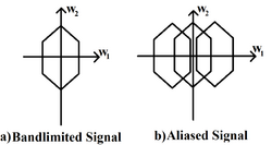
A band limited signal may be periodically replicated in many ways. If the replication results in an overlap between replicated regions, the signal suffers from aliasing. Under such conditions, a continuous time signal cannot be perfectly recovered from its samples. Thus in order to ensure perfect recovery of the continuous signal, there must be zero overlap multidimensional sampling of the replicated regions in the transformed domain. As in the case of 1-dimensional signals, aliasing can be prevented if the continuous time signal is sampled at an adequate sufficiently high rate.
Sampling density
It is a measure of the number of samples per unit area. It is defined as:
- .
The minimum number of samples per unit area required to completely recover the continuous time signal is termed as optimal sampling density. In applications where memory or processing time are limited, emphasis must be given to minimizing the number of samples required to represent the signal completely.
Existing approaches
For a bandlimited waveform, there are infinitely many ways the signal can be sampled without producing aliases in the Fourier domain. But only two strategies are commonly used: rectangular sampling and hexagonal sampling.
Rectangular and Hexagonal sampling

In rectangular sampling, a 2-dimensional signal, for example, is sampled according to the following V matrix:
- where T1 and T2 are the sampling periods along the horizontal and vertical direction respectively.[2]

In hexagonal sampling, the V matrix assumes the following general form:
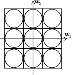
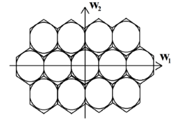
The difference in the efficiency of the two schemes is highlighted using a bandlimited signal with a circular region of support of radius R. The circle can be inscribed in a square of length 2R or a regular hexagon of length . Consequently, the region of support is now transformed into a square and a hexagon respectively. If these regions are periodically replicated in the frequency domain such that there is zero overlap between any two regions, then by periodically replicating the square region of support, we effectively sample the continuous signal on a rectangular lattice. Similarly periodic replication of the hexagonal region of support maps to sampling the continuous signal on a hexagonal lattice.
From U, the periodicity matrix, we can calculate the optimal sampling density for both the rectangular and hexagonal schemes. It is found that in order to completely recover the circularly band-limited signal, the hexagonal sampling scheme requires 13.4% fewer samples than the rectangular sampling scheme. The reduction may appear to be of little significance for a 2-dimensional signal. But as the dimensionality of the signal increases, the efficiency of the hexagonal sampling scheme will become far more evident. For instance, the reduction achieved for an 8-dimensional signal is 93.8%. To highlight the importance of the obtained result [2], try and visualize an image as a collection of infinite number of samples. The primary entity responsible for vision, i.e. the photoreceptors (rods and cones) are present on the retina of all mammals.[3] These cells are not arranged in rows and columns. By adapting a hexagonal sampling scheme, our eyes are able to process images much more efficiently. The importance of hexagonal sampling lies in the fact that the photoreceptors of the human vision system lie on a hexagonal sampling lattice and, thus, perform hexagonal sampling.[3] In fact, it can be shown that the hexagonal sampling scheme is the optimal sampling scheme for a circularly band-limited signal.[4]
Applications
Aliasing effects minimized by the use of optimal sampling grids
Recent advances in the CCD technology has made hexagonal sampling feasible for real life applications. Historically, because of technology constraints, detector arrays were implemented only on 2-dimensional rectangular sampling lattices with rectangular shape detectors. But the super [CCD] detector introduced by Fuji has an octagonal shaped pixel in a hexagonal grid. Theoretically, the performance of the detector was greatly increased by introducing an octagonal pixel. The number of pixels required to represent the sample was reduced and there was significant improvement in the Signal-to-Noise Ratio (SNR) when compared with that of a rectangular pixel.[5] But the drawback of using hexagonal pixels is that the associated fill factor will be less than 82%. An alternative method would be to interpolate hexagonal pixels in such a manner that we ultimately end up with a rectangular grid. The Spot 5 satellite incorporates a similar technique where two identical linear CCD's transmit two quasi-identical images that are shifted by half a pixel. On interpolating the two images and processing them, the functioning of a detector with a hexagonal pixel is mimicked.
Hexagonal structure for Intelligent vision
One of the major challenges encountered in the field of computer graphics is to represent the real world continuous signal as a discrete set of points on the physical screen. It has been long known that hexagonal sampling grids have several benefits compared to rectangular grids. Peterson and Middleton investigated sampling and reconstruction of wave number limited M dimensional functions and came to the conclusion that the optimal sampling lattice, in general, is not hexagonal.[6] Russell M. Mersereau developed hexagonal discrete Fourier transform (DFT) and hexagonal finite extent impulse response filters. He was able to show that for circularly bandlimited signals, hexagonal sampling is more efficient than rectangular sampling. Cramblitt and Allebach developed methods for designing optimal hexagonal time-sequential sampling patterns and discussed their merits relative to those designed for a rectangular sampling grid. [7]

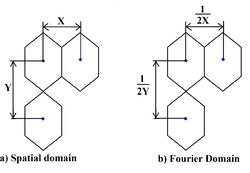
One of the unique features of a hexagonal sampling grid is that its Fourier transform is still hexagonal. There is also an inverse relationship between the distance between successive rows and columns (assuming the samples are located at the centre of the hexagon). This inverse relationship plays a huge role in minimizing aliasing and maximizing the minimum sampling density. Quantization error is bound to be present when discretizing continuous real world signals. Experiments have been performed to determine which detector configuration will yield the least quantization error. Hexagonal spatial sampling was found to yield the least quantization error for a given resolution of the sensor.
Consistent connectivity of hexagonal grids: In a hexagonal grid, we can define only a background of 6 neighborhood samples. However, in a square grid, we can define a background of 4 or 8 neighborhood samples [4] (if diagonal connectivity is permitted). Because of the absence of such a choice in Hexagonal grids, efficient algorithms can be designed. Consistent connectivity is also responsible for better angular resolution. This is why hexagonal lattice is much better at representing curved objects than the rectangular lattice. Despite of these several advantages, hexagonal grids have not been used practically in computer vision to its maximum potential because of the lack of hardware to process, capture and display hexagonal based images. As highlighted earlier with the Spot 5 satellite, one of the methods being looked at to overcome this hardware difficulty is to mimic hexagonal pixels using square pixels.
References
- ↑ Ton Kalker,"On Multidimensional Sampling", Philip Research Laboratories, Eindhoven, chapter 4, section 4.2
- ↑ Dan E. Dudgeon and Russell M. Mersereau, "Multidimensional Digital Signal Processing", Prentice Hall, 1984, chapter 1, pp. 43–44.
- ↑ D.Phil Jonathan, T. Erichsen and J. Margaret Woodhouse,"Human and Animal Vision", Cardiff School of Optometry and Vision Sciences, Cardiff University, Cardiff, UK
- ↑ D. P. Petersen and D. Middleton, "Sampling and Reconstruction of Wave-Number-Limited Functions in N-Dimensional Euclidean Spaces", Information and Control, vol. 5, pp. 279–323, 1962.
- ↑ R. Vitulli, R.; Del Bello, U.; Armbruster, P.; Baronti, S.; Santurti, L. (2002). "Aliasing effects mitigation by optimised sampling grids and impact on image acquisition chains". IEEE International Geoscience and Remote Sensing Symposium. 2. pp. 979. doi:10.1109/IGARSS.2002.1025749. ISBN 0-7803-7536-X.
- ↑ Xiangjian He; Wenjing Jia (2005). "Hexagonal Structure for Intelligent Vision". 2005 International Conference on Information and Communication Technologies. pp. 52. doi:10.1109/ICICT.2005.1598543. ISBN 0-7803-9421-6.
- ↑ R. M. Cramblitt and J. P. Allebach, “Analysis of time-sequential sampling with a spatially hexagonal lattice,” J. Opt. Soc. Am., vol. 73, p. 1510, June, 1983.
 |
