Orientation (geometry)

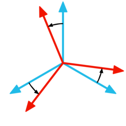
In geometry, the orientation, angular position, attitude, or direction of an object such as a line, plane or rigid body is part of the description of how it is placed in the space it occupies.[1] More specifically, it refers to the imaginary rotation that is needed to move the object from a reference placement to its current placement. A rotation may not be enough to reach the current placement. It may be necessary to add an imaginary translation, called the object's location (or position, or linear position). The location and orientation together fully describe how the object is placed in space. The above-mentioned imaginary rotation and translation may be thought to occur in any order, as the orientation of an object does not change when it translates, and its location does not change when it rotates.
Euler's rotation theorem shows that in three dimensions any orientation can be reached with a single rotation around a fixed axis. This gives one common way of representing the orientation using an axis–angle representation. Other widely used methods include rotation quaternions, rotors, Euler angles, or rotation matrices. More specialist uses include Miller indices in crystallography, strike and dip in geology and grade on maps and signs. Unit vector may also be used to represent an object's normal vector orientation or the relative direction between two points.
Typically, the orientation is given relative to a frame of reference, usually specified by a Cartesian coordinate system.
Mathematical representations
Three dimensions
In general the position and orientation in space of a rigid body are defined as the position and orientation, relative to the main reference frame, of another reference frame, which is fixed relative to the body, and hence translates and rotates with it (the body's local reference frame, or local coordinate system). At least three independent values are needed to describe the orientation of this local frame. Three other values describe the position of a point on the object. All the points of the body change their position during a rotation except for those lying on the rotation axis. If the rigid body has rotational symmetry not all orientations are distinguishable, except by observing how the orientation evolves in time from a known starting orientation. For example, the orientation in space of a line, line segment, or vector can be specified with only two values, for example two direction cosines. Another example is the position of a point on the earth, often described using the orientation of a line joining it with the earth's center, measured using the two angles of longitude and latitude. Likewise, the orientation of a plane can be described with two values as well, for instance by specifying the orientation of a line normal to that plane, or by using the strike and dip angles.
Further details about the mathematical methods to represent the orientation of rigid bodies and planes in three dimensions are given in the following sections.
Two dimensions
In two dimensions the orientation of any object (line, vector, or plane figure) is given by a single value: the angle through which it has rotated. There is only one degree of freedom and only one fixed point about which the rotation takes place.
Rigid body in three dimensions
Several methods to describe orientations of a rigid body in three dimensions have been developed. They are summarized in the following sections.
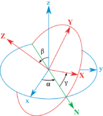
Euler angles

The first attempt to represent an orientation is attributed to Leonhard Euler. He imagined three reference frames that could rotate one around the other, and realized that by starting with a fixed reference frame and performing three rotations, he could get any other reference frame in the space (using two rotations to fix the vertical axis and another to fix the other two axes). The values of these three rotations are called Euler angles.
Tait–Bryan angles

These are three angles, also known as yaw, pitch and roll, Navigation angles and Cardan angles. Mathematically they constitute a set of six possibilities inside the twelve possible sets of Euler angles, the ordering being the one best used for describing the orientation of a vehicle such as an airplane. In aerospace engineering they are usually referred to as Euler angles.

Orientation vector
Euler also realized that the composition of two rotations is equivalent to a single rotation about a different fixed axis (Euler's rotation theorem). Therefore, the composition of the former three angles has to be equal to only one rotation, whose axis was complicated to calculate until matrices were developed.
Based on this fact he introduced a vectorial way to describe any rotation, with a vector on the rotation axis and module equal to the value of the angle. Therefore, any orientation can be represented by a rotation vector (also called Euler vector) that leads to it from the reference frame. When used to represent an orientation, the rotation vector is commonly called orientation vector, or attitude vector.
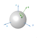
A similar method, called axis–angle representation, describes a rotation or orientation using a unit vector aligned with the rotation axis, and a separate value to indicate the angle (see figure).
Orientation matrix
With the introduction of matrices, the Euler theorems were rewritten. The rotations were described by orthogonal matrices referred to as rotation matrices or direction cosine matrices. When used to represent an orientation, a rotation matrix is commonly called orientation matrix, or attitude matrix.
The above-mentioned Euler vector is the eigenvector of a rotation matrix (a rotation matrix has a unique real eigenvalue). The product of two rotation matrices is the composition of rotations. Therefore, as before, the orientation can be given as the rotation from the initial frame to achieve the frame that we want to describe.
The configuration space of a non-symmetrical object in n-dimensional space is SO(n) × Rn. Orientation may be visualized by attaching a basis of tangent vectors to an object. The direction in which each vector points determines its orientation.
Orientation quaternion
Another way to describe rotations is using rotation quaternions, also called versors. They are equivalent to rotation matrices and rotation vectors. With respect to rotation vectors, they can be more easily converted to and from matrices. When used to represent orientations, rotation quaternions are typically called orientation quaternions or attitude quaternions.
Plane in three dimensions
Miller indices

The attitude of a lattice plane is the orientation of the line normal to the plane,[2] and is described by the plane's Miller indices. In three-space a family of planes (a series of parallel planes) can be denoted by its Miller indices (hkl),[3][4] so the family of planes has an attitude common to all its constituent planes.
Strike and dip

Many features observed in geology are planes or lines, and their orientation is commonly referred to as their attitude. These attitudes are specified with two angles.
For a line, these angles are called the trend and the plunge. The trend is the compass direction of the line, and the plunge is the downward angle it makes with a horizontal plane.[5]
For a plane, the two angles are called its strike (angle) and its dip (angle). A strike line is the intersection of a horizontal plane with the observed planar feature (and therefore a horizontal line), and the strike angle is the bearing of this line (that is, relative to geographic north or from magnetic north). The dip is the angle between a horizontal plane and the observed planar feature as observed in a third vertical plane perpendicular to the strike line.
Usage examples
Rigid body

The attitude of a rigid body is its orientation as described, for example, by the orientation of a frame fixed in the body relative to a fixed reference frame. The attitude is described by attitude coordinates, and consists of at least three coordinates.[6] One scheme for orienting a rigid body is based upon body-axes rotation; successive rotations three times about the axes of the body's fixed reference frame, thereby establishing the body's Euler angles.[7][8] Another is based upon roll, pitch and yaw,[9] although these terms also refer to incremental deviations from the nominal attitude
See also
- Angular displacement
- Attitude control
- Directional statistics
- Personal relative direction
- Plane of rotation
- Rotation formalisms in three dimensions
- Triad Method
References
- ↑ Robert J. Twiss; Eldridge M. Moores (1992). "§2.1 The orientation of structures". Structural Geology (2nd ed.). Macmillan. p. 11. ISBN 0-7167-2252-6. https://books.google.com/books?id=14fn03iJ2r8C&q=attitude+plane+orientation&pg=PA11. "...the attitude of a plane or a line — that is, its orientation in space — is fundamental to the description of structures."
- ↑ William Anthony Granville (1904). "§178 Normal line to a surface". Elements of the Differential and Integral Calculus. Ginn & Company. p. 275. https://archive.org/details/elementsdiffere02goog.
- ↑ Augustus Edward Hough Love (1892). A Treatise on the Mathematical Theory of Elasticity. 1. Cambridge University Press. p. 79 ff. https://books.google.com/books?id=-GkSAAAAIAAJ&pg=PA79.
- ↑ Marcus Frederick Charles Ladd; Rex Alfred Palmer (2003). "§2.3 Families of planes and interplanar spacings". Structure Determination by X-Ray Crystallography (4th ed.). Springer. p. 62 ff. ISBN 0-306-47454-9. https://books.google.com/books?id=vNJrAe36BBMC&pg=PA62.
- ↑ Stephen Mark Rowland; Ernest M. Duebendorfer; Ilsa M. Schiefelbein (2007). "Attitudes of lines and planes". Structural Analysis and Synthesis: A Laboratory Course in Structural Geology (3rd ed.). Wiley-Blackwell. p. 1 ff. ISBN 978-1-4051-1652-7. https://books.google.com/books?id=IWnmBEtmg2MC&q=%22attitude+of+a+line%22&pg=PR3.
- ↑ Hanspeter Schaub; John L. Junkins (2003). "Rigid body kinematics". Analytical Mechanics of Space Systems. American Institute of Aeronautics and Astronautics. p. 71. ISBN 1-56347-563-4. https://books.google.com/books?id=qXvESNWrfpUC&q=attitude+%22rigid+body%22&pg=PA71.
- ↑ Jack B. Kuipers (2002). "Figure 4.7: Aircraft Euler angle sequence". Quaternions and Rotation Sequences: A Primer with Applications to Orbits, Aerospace, and Virtual Reality. Princeton University Press. p. 85. ISBN 0-691-10298-8. https://books.google.com/books?id=_2sS4mC0p-EC&pg=PA85.
- ↑ Bong Wie (1998). "§5.2 Euler angles". Space Vehicle Dynamics and Control. American Institute of Aeronautics and Astronautics. p. 310. ISBN 1-56347-261-9. https://archive.org/details/spacevehicledyna00wieb_0. "Euler angle rigid body attitude."
- ↑ Lorenzo Sciavicco; Bruno Siciliano (2000). "§2.4.2 Roll–pitch–yaw angles". Modelling and Control of Robot Manipulators (2nd ed.). Springer. p. 32. ISBN 1-85233-221-2. https://books.google.com/books?id=v9PLbcYd9aUC&pg=PA32.
External links
 |
