Physics:Hertz vector
| Part of a series of articles about |
| Electromagnetism |
|---|
 |
Hertz vectors, or the Hertz vector potentials, are an alternative formulation of the electromagnetic potentials. They are most often introduced in electromagnetic theory textbooks as practice problems for students to solve.[1] There are multiple cases where they have a practical use, including antennas[2] and waveguides.[3] Though they are sometimes used in such practice problems, they are still rarely mentioned in most electromagnetic theory courses, and when they are they are often not practiced in a manner that demonstrates when they may be useful or provide a simpler method to solving a problem than more commonly practiced methods.[citation needed]
Overview
Hertz vectors can be advantageous when solving for the electric and magnetic fields in certain scenarios, as they provide an alternative way to define the scalar potential [math]\displaystyle{ \phi }[/math] and the vector potential [math]\displaystyle{ \mathbf{A} }[/math] which are used to find the fields as is commonly done.
[math]\displaystyle{ \mathbf{E} = -\nabla \phi - \frac{\partial \mathbf{A}}{\partial t} }[/math] |
|
() |
[math]\displaystyle{ \mathbf{B} = \nabla \times \mathbf{A} }[/math] |
|
() |
Considering cases of electric and magnetic polarization separately for simplicity, each can be defined in terms of the scalar and vector potentials which then allows for the electric and magnetic fields to be found. For cases of just electric polarization the following relations are used.
[math]\displaystyle{ \phi = - \nabla\cdot\mathbf{\Pi}_e }[/math] |
|
() |
[math]\displaystyle{ \mathbf{A}=\mu\epsilon\frac{\partial\mathbf{\Pi}_e}{\partial t} }[/math] |
|
() |
And for cases of solely magnetic polarization they are defined as:
[math]\displaystyle{ \phi = 0 }[/math] |
|
() |
[math]\displaystyle{ \mathbf{A}=\nabla\times\mathbf{\Pi}_m }[/math] |
|
() |
To apply these, the polarizations need to be defined so that the form of the Hertz vectors can be obtained. Considering the case of simple electric polarization provides the path to finding this form via the wave equation. Assuming the space is uniform and non-conducting, and the charge and current distributions are given by [math]\displaystyle{ \rho(\mathbf{r},t), \mathbf{J}(\mathbf{r},t) }[/math], define a vector [math]\displaystyle{ \mathbf{P}=\mathbf{P}(\mathbf{r},t) }[/math] such that [math]\displaystyle{ \rho = -\nabla \cdot \mathbf{P} }[/math] and [math]\displaystyle{ \mathbf{J}= \frac{\partial\mathbf{P}}{\partial t} }[/math]. Using these to solve for the [math]\displaystyle{ \mathbf{\Pi} }[/math] vectors is similar to how the auxiliary fields [math]\displaystyle{ \mathbf{D} }[/math] and [math]\displaystyle{ \mathbf{H} }[/math] can be found, however here the Hertz vectors treat the electric and magnetic polarizations as sources. The Hertz vector potentials from these sources, [math]\displaystyle{ \mathbf{\Pi}_e }[/math] for the electric Hertz potential, and [math]\displaystyle{ \mathbf{\Pi}_m }[/math] for the magnetic Hertz potential can be derived using the wave equation for each.
[math]\displaystyle{ \nabla^2\mathbf{\Pi}_e - \mu \epsilon \frac{\partial^2 \mathbf{\Pi}_e}{\partial t^2} = -\frac{\mathbf{P}}{\epsilon} }[/math] |
|
() |
[math]\displaystyle{ \nabla^2\mathbf{\Pi}_m - \mu \epsilon \frac{\partial^2 \mathbf{\Pi}_m}{\partial t^2} = -\mu \mathbf{M} }[/math] |
|
() |
This is simply done by applying the d'Alembert operator [math]\displaystyle{ \Box=\left(\nabla^2-\frac{1}{c^2}\frac{\partial^2}{\partial t^2}\right) }[/math] to both vectors, keeping in mind that [math]\displaystyle{ c^2 = \left(\mu \epsilon\right)^{-1} }[/math], and the result is non-zero due to the polarizations that are present. This provides a direct pathway between easily determined properties such as current density [math]\displaystyle{ \mathbf{J} }[/math] to fields via the Hertz vectors and their relations to the scalar and vector potentials. These wave equations yield the following solutions for the Hertz vectors:
[math]\displaystyle{ \mathbf{\Pi}_e = \frac{1}{4 \pi \epsilon} \int\limits_V \frac{\left[\mathbf{P}\left(\mathbf{r}'\right)\right]}{|\mathbf{r}-\mathbf{r}'|}d^3\mathbf{r}' }[/math] |
|
() |
[math]\displaystyle{ \mathbf{\Pi}_m = \frac{\mu}{4 \pi} \int\limits_V \frac{\left[\mathbf{M}\left(\mathbf{r}'\right)\right]}{|\mathbf{r}-\mathbf{r}'|}d^3\mathbf{r}' }[/math] |
|
() |
where [math]\displaystyle{ \left[\mathbf{P}\left(\mathbf{r}'\right)\right] }[/math] and [math]\displaystyle{ \left[\mathbf{M}\left(\mathbf{r}'\right)\right] }[/math] should be evaluated at the retarded time [math]\displaystyle{ |\mathbf{r}-\mathbf{r'}|/v }[/math].[1] The electric and magnetic fields can then be found using the Hertz vectors. For simplicity in observing the relationship between polarization, the Hertz vectors, and the fields, only one source of polarization (electric or magnetic) will be considered at a time. In the absence of any magnetic polarization, the [math]\displaystyle{ \mathbf{\Pi}_e }[/math] vector is used to find the fields as follows:
[math]\displaystyle{ \mathbf{E}=\nabla\left(\nabla\cdot\mathbf{\Pi}_e\right)-\mu\epsilon\frac{\partial^2\mathbf{\Pi}_e}{\partial t^2} }[/math] |
|
() |
[math]\displaystyle{ \mathbf{B}=\mu\epsilon\frac{\partial}{\partial t}\left(\nabla\times\mathbf{\Pi}_e\right) }[/math] |
|
() |
Similarly, in the case of only magnetic polarization being present, the fields are determined via the previously stated relations to the scalar and vector potentials.
[math]\displaystyle{ \mathbf{E}=-\frac{\partial}{\partial t}\left(\nabla\times\mathbf{\Pi}_m\right) }[/math] |
|
() |
[math]\displaystyle{ \mathbf{B}=\nabla\times\nabla\times\mathbf{\Pi}_m }[/math] |
|
() |
For the case of both electric and magnetic polarization being present, the fields become
[math]\displaystyle{ \mathbf{E} = \nabla \times \nabla \times\mathbf{\Pi}_e -\nabla \times \frac{\partial\mathbf{\Pi}_m}{\partial t} }[/math] |
|
() |
[math]\displaystyle{ \mathbf{B} = \nabla \times \nabla \times\mathbf{\Pi}_m -\nabla \times \frac{\partial\mathbf{\Pi}_e}{\partial t} }[/math] |
|
() |
Examples
Oscillating dipole
Consider a one dimensional, uniformly oscillating current. The current is aligned along the z-axis in some length of conducting material ℓ with an oscillation frequency [math]\displaystyle{ \omega }[/math]. We will define the polarization vector
[math]\displaystyle{ \mathbf{P}=(-I\ell/\omega) \cos\left[\omega t\right]_{t'}\mathbf{\hat{z}} }[/math] |
|
() |
where t is evaluated at the retarded time [math]\displaystyle{ t' = t-|\mathbf{r}-\mathbf{r}'|/v }[/math]. Inserting this into the electric Hertz vector equation knowing that the length ℓ is small and the polarization is in one dimension it can be approximated in spherical coordinates as follows
[math]\displaystyle{ \mathbf{\Pi}_e = \frac{1}{4\pi\epsilon}\frac{\left(-I\ell/\omega\right)\cos\left[\omega t\right]_{t'}}{|\mathbf{r}-\mathbf{r}'|}\left[\cos\left(\theta\right)\mathbf{\hat{r}}-\sin\left(\theta\right)\mathbf{\hat{\theta}}\right] }[/math] |
|
() |
Continuing directly to taking the divergence quickly becomes messy due to the [math]\displaystyle{ |\mathbf{r}-\mathbf{r'}| }[/math] denominator. This is readily resolved by using Legendre Polynomials for expanding a [math]\displaystyle{ 1/r }[/math] potential:
[math]\displaystyle{ \frac{1}{|\mathbf{x}-\mathbf{x}'|} = \sum_{\ell=0}^{\infty}\frac{r'^\ell}{r^{\ell+1}} P_\ell\left(\cos \gamma\right) }[/math] |
|
() |
It is important to note that in the above equation, [math]\displaystyle{ \mathbf{x} }[/math] and [math]\displaystyle{ \mathbf{x}' }[/math] are vectors, while [math]\displaystyle{ r }[/math] and [math]\displaystyle{ r' }[/math] are the lengths of those vectors. [math]\displaystyle{ \gamma }[/math] is the angle between the vectors [math]\displaystyle{ \mathbf{x} }[/math] and [math]\displaystyle{ \mathbf{x}' }[/math]. The Hertz vector is now written as follows.
[math]\displaystyle{ \mathbf{\Pi}_e = \frac{\left(-I\ell/\omega\right)\cos\left[\omega t\right]_{t'}}{4\pi\epsilon} \sum_{\ell=0}^{\infty}\frac{r'^\ell}{r^{\ell+1}} P_\ell\left(\cos \gamma\right)\left[\cos\left(\theta\right)\mathbf{\hat{r}}-\sin\left(\theta\right)\boldsymbol{\hat{\theta}}\right] }[/math] |
|
() |
Taking the divergence
[math]\displaystyle{ \nabla\cdot\mathbf{\Pi}_e = \frac{\left(I\ell/\omega\right)\cos\left[\omega t\right]_{t'}\cos\left(\theta\right)}{4\pi\epsilon}\sum_{\ell=0}^{\infty} \frac{r'^\ell\left(\ell+1\right)}{r^{\ell+2}}P_\ell\left(\cos \gamma\right) }[/math] |
|
() |
Then the gradient of the result
[math]\displaystyle{ \nabla\left(\nabla\cdot\mathbf{\Pi}_e\right) = \frac{\left(-I\ell/\omega\right)\cos\left[\omega t\right]_{t'}}{4\pi\epsilon}\sum_{\ell=0}^{\infty}\frac{r'^\ell\left(\ell+1\right)P_\ell\left(\cos\gamma\right)}{r^{\ell+3}}\left[\left(\ell+2\right)\cos\left(\theta\right)\mathbf{\hat{r}}+\sin\left(\theta\right)\mathbf{\hat{\theta}}\right] }[/math] |
|
() |
Finally finding the second partial with respect to time
[math]\displaystyle{ \mu \epsilon \frac{\partial^2 \mathbf{\Pi}_e}{\partial t^2}=\frac{\mu I \ell \omega \cos\left[\omega t\right]_{t'}}{4 \pi}\sum_{\ell=0}^{\infty}\frac{r'^\ell}{r^{\ell+1}}P_\ell\left(\cos \gamma\right)\left[\cos\left(\theta\right)\mathbf{\hat{r}}-\sin\left(\theta\right)\mathbf{\hat{\theta}}\right] }[/math] |
|
() |
Allows for finding the electric field
[math]\displaystyle{ \mathbf{E}=\nabla\left(\nabla\cdot\mathbf{\Pi}_e\right)-\mu\epsilon\frac{\partial^2\mathbf{\Pi}_e}{\partial t^2}=\frac{I\ell\cos\left[\omega t\right]_{t'}}{4\pi} \sum_{\ell=0}^{\infty}\frac{r'^\ell P_\ell\left(\cos\left(\gamma\right)\right)}{r^{\ell+1}}\left[\left(\frac{-\left(\ell+1\right)\left(\ell+2\right)}{r^2\epsilon\omega}-\mu\omega\right)\cos\left(\theta\right)\mathbf{\hat{r}} + \left(\frac{-\left(\ell+1\right)}{r^2\epsilon\omega}+\mu\omega\right)\sin\left(\theta\right)\mathbf{\hat{\theta}}\right] }[/math] |
|
() |
Simulation
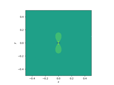
Using the appropriate conversions to Cartesian coordinates, this field can be simulated in a 3D grid. Viewing the X-Y plane at the origin shows the two-lobed field in one plane we expect from a dipole, and it oscillates in time. The image below shows the shape of this field and how the polarity reverses in time due to the cosine term, however it does not currently show the amplitude change due to the time varying strength of the current. Regardless, its shape alone shows the effectiveness of using the electric Hertz vector in this scenario. This approach is significantly more straightforward than finding the electric field in terms of charges within the infinitely thin wire, especially as they vary with time. This is just one of several examples of when the use of Hertz vectors is advantageous compared to more common methods.
Current loop
Consider a small loop of area [math]\displaystyle{ A }[/math] carrying a time varying current [math]\displaystyle{ I \sin\left(\omega t\right) }[/math]. With current flow, a magnetic field perpendicular to the direction of flow as a result of the right hand rule will be present. Due to this field being generated in a loop, it is expected that the field would look similar to that of an electric dipole. This can be proven quickly using Hertz vectors. First the magnetic polarization is determined by its relation to magnetic moment [math]\displaystyle{ \mathbf{M}=\frac{d\mathbf{m}}{dV} }[/math]. The magnetic moment of a current loop is defined as [math]\displaystyle{ \mathbf{m}=IA\mathbf{\hat{n}} }[/math], so if the loop lies in the x-y plane and has the previously defined time-varying current, the magnetic moment is [math]\displaystyle{ \mathbf{m}=IA \sin\left(\omega t\right)\mathbf{\hat{z}} }[/math]. Inserting this into [math]\displaystyle{ \mathbf{M} }[/math], and then into Equation (10), the magnetic Hertz vector is found in a simple form.
[math]\displaystyle{ \mathbf{\Pi}_m=\frac{\mu I A \sin\left(\omega t\right)}{4 \pi|\mathbf{r}-\mathbf{r}'|}\mathbf{\hat{z}} }[/math] |
|
() |
As in the electric dipole example, the Legendre polynomials can be used to simplify the derivatives necessary to obtain [math]\displaystyle{ \mathbf{E} }[/math] and [math]\displaystyle{ \mathbf{B} }[/math]. The electric field is then found through
[math]\displaystyle{ \mathbf{E}=-\frac{\partial}{\partial t}\left(\nabla\times\frac{\mu I A \sin\left(\omega t\right)}{4\pi}\sum_{\ell=0}^{\infty}\frac{r'^\ell}{r^{\ell+1}}P_\ell\left(\cos \gamma\right)\right)\mathbf{\hat{z}} }[/math] |
|
() |
Due to the dependence on [math]\displaystyle{ r }[/math], it is significantly simpler to express the Hertz vector in spherical coordinates by transforming from the sole [math]\displaystyle{ \mathbf{\hat{z}} }[/math] component vector to the [math]\displaystyle{ \mathbf{\hat{r}} }[/math] and [math]\displaystyle{ \mathbf{\hat{\theta}} }[/math] components.
[math]\displaystyle{ \mathbf{E}=-\frac{\partial}{\partial t}\left(\nabla\times\frac{\mu I A \sin\left(\omega t\right)}{4\pi}\sum_{\ell=0}^{\infty}\frac{r'^\ell}{r^{\ell+1}}P_\ell\left(\cos \gamma\right)\left[\cos\left(\theta\right)\mathbf{\hat{r}}-\sin\left(\theta\right)\mathbf{\hat{\theta}}\right]\right) }[/math] |
|
() |
[math]\displaystyle{ \mathbf{E}=\frac{-\mu A I \omega \cos\left(\omega t\right)}{4 \pi}\cos\left(\theta\right)\sum_{\ell=0}^{\infty}\frac{r'^\ell}{r^{\ell+2}}P_\ell\left(\cos \gamma\right)\left(1-\ell\right)\mathbf{\hat{\phi}} }[/math] |
|
() |
Simulation
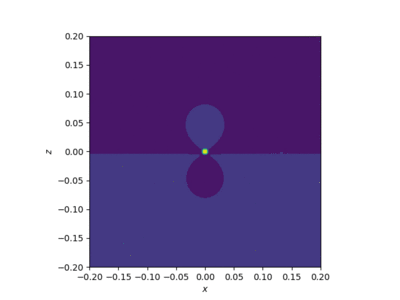
This field was simulated using Python by converting the spherical component to x and y components. The result is as expected. Due to the changing current, there is a time dependent magnetic field which induces an electric field. Due to the shape, the field appears as if it were a dipole.
See also
References
- ↑ 1.0 1.1 E.A. Essex, "Hertz vector potentials of electromagnetic theory", American Journal of Physics 45, 1099 (1977); doi: 10.1119/1.10955
- ↑ J. Galejs, Antennas in Inhomogeneous Media, (Pregamon, Oxford,1969).
- ↑ H. R. L. Lamont, Wave Guides, (Metheun, London, 1963).
 |


