Astronomy:X-ray astronomy detector

X-ray astronomy detectors are instruments that detect X-rays for use in the study of X-ray astronomy.
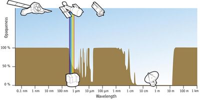
X-ray astronomy is an observational branch of astronomy which deals with the study of X-ray emission from celestial objects. X-radiation is absorbed by the Earth's atmosphere, so instruments to detect X-rays must be taken to high altitude by balloons, sounding rockets, and satellites. X-ray astronomy is part of space science.
X-ray astronomy detectors have been designed and configured primarily for energy and occasionally for wavelength detection using a variety of techniques usually limited to the technology of the time.
Detection and imaging of X-rays
X-rays span 3 decades in wavelength (~8 nm - 8 pm), frequency (~50 PHz - 50 EHz) and energy (~0.12 - 120 keV). In terms of temperature, 1 eV = 11,604 K. Thus X-rays (0.12 to 120 keV) correspond to 1.39 × 10⁶ to 1.39 × 10⁹ K. From 10 to 0.1 nanometers (nm) (about 0.12 to 12 keV) they are classified as soft X-rays, and from 0.1 nm to 0.01 nm (about 12 to 120 keV) as hard X-rays.
Closer to the visible range of the electromagnetic spectrum is the ultraviolet. The draft ISO standard on determining solar irradiances (ISO-DIS-21348)[1] describes the ultraviolet as ranging from ~10 nm to ~400 nm. That portion closest to X-rays is often referred to as the "extreme ultraviolet" (EUV or XUV). When an EUV photon is absorbed, photoelectrons and secondary electrons are generated by ionization, much like what happens when X-rays or electron beams are absorbed by matter.[2]
The distinction between X-rays and gamma rays has changed in recent decades. Originally, the electromagnetic radiation emitted by X-ray tubes had a longer wavelength than the radiation emitted by radioactive nuclei (gamma rays).[3] So older literature distinguished between X- and gamma radiation on the basis of wavelength, with radiation shorter than some arbitrary wavelength, such as 10−11 m, defined as gamma rays.[4] However, as shorter wavelength continuous spectrum "X-ray" sources such as linear accelerators and longer wavelength "gamma ray" emitters were discovered, the wavelength bands largely overlapped. The two types of radiation are now usually distinguished by their origin: X-rays are emitted by electrons outside the nucleus, while gamma rays are emitted by the nucleus.[3][5][6][7]
Although the more energetic X-rays, photons with an energy greater than 30 keV (4,800 aJ), can penetrate the air at least for distances of a few meters, the Earth's atmosphere is thick enough that virtually none are able to penetrate from outer space all the way to the Earth's surface (they would have been detected and medical X-ray machines would not work if this was not the case). X-rays in the 0.5 to 5 keV (80 to 800 aJ) range, where most celestial sources give off the bulk of their energy, can be stopped by a few sheets of paper; 90% of the photons in a beam of 3 keV (480 aJ) X-rays are absorbed by traveling through just 10 cm of air.
To detect X-rays from the sky, X-ray detectors must be flown above most of the Earth's atmosphere. There are three main methods of doing so: sounding rocket flights, balloons, and satellites.
Proportional counters
A proportional counter is a type of gaseous ionization detector that counts particles of ionizing radiation and measures their energy. It works on the same principle as the Geiger-Müller counter, but uses a lower operating voltage. All X-ray proportional counters consist of a windowed gas cell.[8] Often this cell is subdivided into a number of low- and high-electric field regions by some arrangement of electrodes.
An individual medium energy proportional counter on EXOSAT had a front window of beryllium with aluminized kapton foil for thermal protection, a front chamber filled with an argon/CO2 mixture, a rear chamber with xenon/CO2, and a beryllium window separating the two chambers.[9] The argon portion of the detector was optimized for 2-6 keV and the total energy ranges for both detectors was 1.5-15 keV and 5-50 keV, respectively.
The US portion of the Apollo–Soyuz mission (July 1975) carried a proportional counter system sensitive to 0.18-0.28 and 0.6-10.0 keV X-rays. The total effective area was 0.1 m2, and there was a 4.5° FWHM circular FOV.
The French TOURNESOL instrument consisted of four proportional counters and two optical detectors. The proportional counters detected photons between 2 keV and 20 MeV in a 6° × 6° FOV. The visible detectors had a field of view of 5° × 5°. The instrument was designed to look for optical counterparts of high-energy burst sources, as well as performing spectral analysis of the high-energy events.[10]
X-ray monitor
Monitoring generally means to be aware of the state of a system. A device that displays or sends a signal for displaying X-ray output from an X-ray generating source so as to be aware of the state of the source is referred to as an X-ray monitor in space applications. On Apollo 15 in orbit above the Moon, for example, an X-ray monitor was used to follow the possible variation in solar X-ray intensity and spectral shape while mapping the lunar surface with respect to its chemical composition due to the production of secondary X-rays.[11]
The X-ray monitor of Solwind, designated NRL-608 or XMON, was a collaboration between the Naval Research Laboratory and Los Alamos National Laboratory. The monitor consisted of 2 collimated argon proportional counters. The instrument bandwidth of 3-10 keV was defined by the detector window absorption (the window was 0.254 mm beryllium) and the upper level discriminator. The active gas volume (P-10 mixture) was 2.54 cm deep, providing good efficiency up to 10 keV. Counts were recorded in 2 energy channels. Slat collimators defined a FOV of 3° × 30° (FWHM) for each detector; the long axes of the FOVs were perpendicular to each other. The long axes were inclined 45° to the scan direction, allowing localization of transient events to about 1°. The centers of the FOVs coincided, and were pointed 40° below the scan equator of the wheel in order to avoid scanning across the Sun. The spacecraft wheel rotated once every 6 seconds. This scan rate corresponds to 1° every 16 milliseconds (ms); counts were telemetered in 64 or 32 ms bins to minimize smearing the collimator response.
The instrument parameters and data yield implied a 3 σ point source sensitivity of 30 UFU in one day's operation (1 UFU = 2.66−12 erg/cm2-s-keV). Each detector was about 0.1 of the area of the Uhuru instrument. The instrument background at low geomagnetic latitudes was ~16 counts/s. Of this background, ~6 counts/s comes from the diffuse cosmic X-ray background, with the rest being instrumental. Assuming a conservative 10% data return, the net source duty cycle in scanning mode was 1.4 × 10⁻³, implying a source exposure of 120 seconds per day. For a background of 16 counts/s, the 3 σ error in determining the flux from a given sky bin was then 4.5 counts/s, or about 45 UFU, after 1 day. A limiting sensitivity of 30 UFU was obtained by combining both detectors. A comparable error existed in the flux determination for moderately bright galactic sources. Source confusion due to the 5° FOV projected along the scan direction complicated the observation of sources in the galactic bulge region (approximately 30° > l > -30°, |b| < 10°).
Scintillation detector
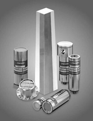
A scintillator is a material which exhibits the property of luminescence[12] when excited by ionizing radiation. Luminescent materials, when struck by an incoming particle, such as an X-ray photon, absorb its energy and scintillate, i.e. reemit the absorbed energy in the form of a small flash of light, typically in the visible range.
The scintillation X-ray detector (XC) aboard Vela 5A and its twin Vela 5B consisted of two 1 mm thick NaI(Tl) crystals mounted on photomultiplier tubes and covered by a 0.13 mm thick beryllium window. Electronic thresholds provided two energy channels, 3-12 keV and 6-12 keV.[13] In front of each crystal was a slat collimator providing a full width at half maximum (FWHM) aperture of ~6.1 × 6.1°. The effective detector area was ~26 cm2. Sensitivity to celestial sources was severely limited by the high intrinsic detector background.
The X-ray telescope onboard OSO 4 consisted of a single thin NaI(Tl) scintillation crystal plus phototube assembly enclosed in a CsI(Tl) anti-coincidence shield. The energy resolution was 45% at 30 keV. The instrument operated from ~8 to 200 keV with 6 channel resolution.
OSO 5 carried a CsI crystal scintillator. The central crystal was 0.635 cm thick, had a sensitive area of 70 cm2, and was viewed from behind by a pair of photomultiplier tubes. The shield crystal had a wall thickness of 4.4 cm and was viewed by 4 photomultipliers. The field of view was ~40°. The energy range covered was 14-254 keV. There were 9 energy channels: the first covering 14-28 keV and the others equally spaced from 28 to 254 keV. In-flight calibration was done with an 241Am source.
The PHEBUS experiment recorded high energy transient events in the range 100 keV to 100 MeV. It consisted of two independent detectors and their associated electronics. Each detector consisted of a bismuth germinate (BGO) crystal 78 mm in diameter by 120 mm thick, surrounded by a plastic anti-coincidence jacket. The two detectors were arranged on the spacecraft so as to observe 4π steradians. The burst mode was triggered when the count rate in the 0.1 to 1.5 MeV energy range exceeded the background level by 8 σ (standard deviations) in either 0.25 or 1.0 seconds. There were 116 channels over the energy range.[10]
The KONUS-B instrument consisted of seven detectors distributed around the spacecraft that responded to photons of 10 keV to 8 MeV energy. They consisted of NaI(Tl) scintillator crystals 200 mm in diameter by 50 mm thick behind a Be entrance window. The side surfaces were protected by a 5 mm thick lead layer. The burst detection threshold was 5 × 10⁻⁷ to 5 × 10⁻⁸ ergs/cm2, depending on the burst spectrum and rise time. Spectra were taken in two 31-channel pulse height analyzers (PHAs), of which the first eight were measured with 1/16 s time resolution and the remaining with variable time resolutions depending on the count rate. The range of resolutions covered 0.25 to 8 s.
Kvant-1 carried the HEXE, or High Energy X-ray Experiment, which employed a phoswich of sodium iodide and caesium iodide. It covered the energy range 15-200 keV with a 1.6° × 1.6° FOV FWHM. Each of the 4 identical detectors had a geometric area of 200 cm2. The maximum time resolution was 0.3-25 ms.
Modulation collimator
In electronics, modulation is the process of varying one waveform in relation to another waveform. With a 'modulation collimator' the amplitude (intensity) of the incoming X-rays is reduced by the presence of two or more 'diffraction gratings' of parallel wires that block or greatly reduce that portion of the signal incident upon the wires.
An X-ray collimator is a device that filters a stream of X-rays so that only those traveling parallel to a specified direction are allowed through.
Minoru Oda, President of Tokyo University of Information Sciences, invented the modulation collimator, first used to identify the counterpart of Sco X-1 in 1966, which led to the most accurate positions for X-ray sources available, prior to the launch of X-ray imaging telescopes.[14]
SAS 3 carried modulation collimators (2-11 keV) and Slat and Tube collimators (1 up to 60keV).[15]
On board the Granat International Astrophysical Observatory were four WATCH instruments that could localize bright sources in the 6 to 180 keV range to within 0.5° using a Rotation Modulation Collimator. Taken together, the instruments' three fields of view covered approximately 75% of the sky. The energy resolution was 30% FWHM at 60 keV. During quiet periods, count rates in two energy bands (6 to 15 and 15 to 180 keV) were accumulated for 4, 8, or 16 seconds, depending on onboard computer memory availability. During a burst or transient event, count rates were accumulated with a time resolution of 1 s per 36 s.[10]
The Reuven Ramaty High Energy Solar Spectroscopic Imager (RHESSI), Explorer 81, images solar flares from soft X-rays to gamma rays (~3 keV to ~20 MeV). Its imaging capability is based on a Fourier-transform technique using a set of 9 Rotational Modulation Collimators.
X-ray spectrometer
OSO 8 had on board a Graphite Crystal X-ray Spectrometer, with energy range of 2-8 keV, FOV 3°.
The Granat ART-S X-ray spectrometer covered the energy range 3 to 100 keV, FOV 2° × 2°. The instrument consisted of four detectors based on spectroscopic MWPCs, making an effective area of 2,400 cm2 at 10 keV and 800 cm2 at 100 keV. The time resolution was 200 microseconds.[10]
The X-ray spectrometer aboard ISEE-3 was designed to study both solar flares and cosmic gamma-ray bursts over the energy range 5-228 keV. The detector provided full-time coverage, 3π FOV for E > 130 keV, time resolution of 0.25 ms, and absolute timing to within 1 ms. It was intended to be a part of a long-baseline interferometry network of widely separated spacecraft. The efforts were aimed primarily at determining the origin of the bursts through precise directional information established by such a network. The experiment consisted of 2 cylindrical X-ray detectors: a Xenon filled proportional counter covering 5-14 keV, and a NaI(Tl) scintillator covering 12-1250 keV. The proportional counter was 1.27 cm in diameter and was filled with a mixture of 97% Xenon and 3% carbon dioxide. The central part of the counter body was made of 0.51 mm thick beryllium and served as the X-ray entrance window. The scintillator consisted of a 1.0 cm thick cylindrical shell of NaI(Tl) crystal surrounded on all sides by 0.3 cm thick plastic scintillator. The central region, 4.1 cm in diameter, was filled by a quartz light pipe. The whole assembly was enclosed (except for one end) in a 0.1 cm thick beryllium container. The energy channel resolution and timing resolution could be selected by commands sent to the spacecraft. The proportional counter could have up to 9 channels with 0.5 s resolution; the NaI scintillator could have up to 16 channels and 0.00025 s resolution.
CCDs
Most existing X-ray telescopes use CCD detectors, similar to those in visible-light cameras. In visible-light, a single photon can produce a single electron of charge in a pixel, and an image is built up by accumulating many such charges from many photons during the exposure time. When an X-ray photon hits a CCD, it produces enough charge (hundreds to thousands of electrons, proportional to its energy) that the individual X-rays have their energies measured on read-out.
Microcalorimeters
Microcalorimeters can only detect X-rays one photon at a time (but can measure the energy of each).
Transition edge sensors
TES devices are the next step in microcalorimetry. In essence they are super-conducting metals kept as close as possible to their transition temperature. This is the temperature at which these metals become super-conductors and their resistance drops to zero. These transition temperatures are usually just a few degrees above absolute zero (usually less than 10 K).
See also
- X-ray telescope
- X-Ray telescope articles
References
- ↑ Tobiska, W; Nusinov, A (2006). "ISO 21348 Process for Determining Solar Irradiances". 36Th Cospar Scientific Assembly 36: 2621. Bibcode: 2006cosp...36.2621T. http://www.spacewx.com/ISO_solar_standard.html.
- ↑ Henke BL (1977). "0.1–10-keV X-ray induced electron emissions from solids—Models and secondary electron measurements". Journal of Applied Physics 48 (5): 1852. doi:10.1063/1.323938. Bibcode: 1977JAP....48.1852H.
- ↑ 3.0 3.1 Dendy PP; Heaton B (1999). Physics for Diagnostic Radiology. CRC Press. p. 12. ISBN 978-0-7503-0591-4. https://books.google.com/books?id=1BTQvsQIs4wC&pg=PA12.
- ↑ Charles Hodgman, ed (1961). CRC Handbook of Chemistry and Physics (44th ed.). Chemical Rubber Co.. p. 2850.
- ↑ Feynman R; Leighton R; Sands M (1963). The Feynman Lectures on Physics. 1. Addison-Wesley. pp. 2–5. ISBN 978-0-201-02116-5.
- ↑ L'Annunziata M; Baradei M (2003). Handbook of Radioactivity Analysis. Academic Press. p. 58. ISBN 978-0-12-436603-9. https://books.google.com/books?id=b519e10OPT0C&pg=PA58.
- ↑ Grupen C; Cowan G; Eidelman SD; Stroh T (2005). Astroparticle Physics. Springer. p. 109. ISBN 978-3-540-25312-9.
- ↑ "Proportional Counters". http://imagine.gsfc.nasa.gov/docs/science/how_l2/proportional.html.
- ↑ Hoff HA (1983). "Exosat - the new extrasolar X-ray observatory". J. Br. Interplanet. Soc. 36: 363. Bibcode: 1983JBIS...36..363H.
- ↑ 10.0 10.1 10.2 10.3 "Granat". NASA. http://heasarc.gsfc.nasa.gov/docs/granat/granat_about.html.
- ↑ Adler I; Gerard J; Trombka J; Schmadebeck R; Lowman P; Bodgett H (1972). "The Apollo 15 x-ray fluorescence experiment". Proc Lunar Sci Conf 2: 2157. Bibcode: 1972LPSC....3.2157A.
- ↑ Leo WR (1994). Techniques for Nuclear and particle Physics Experiments (2nd ed.). Springer.
- ↑ Conner JP; Evans WD; Belian RD (1969). "The Recent Appearance of a New X-Ray Source in the Southern Sky". Astrophys J 157: L157. doi:10.1086/180409. Bibcode: 1969ApJ...157L.157C.
- ↑ Cominsky L; Inoue H. "Minoru Oda (1923 - 2001)". http://www.aas.org/head/headnews/headnews.may01.html.
- ↑ "The Third Small Astronomy Satellite (SAS-3)". http://imagine.gsfc.nasa.gov/docs/sats_n_data/missions/sas3.html.


