Earth:Ice core
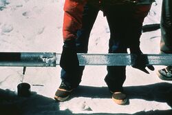
An ice core is a core sample that is typically removed from an ice sheet or a high mountain glacier. Since the ice forms from the incremental buildup of annual layers of snow, lower layers are older than upper ones, and an ice core contains ice formed over a range of years. Cores are drilled with hand augers (for shallow holes) or powered drills; they can reach depths of over two miles (3.2 km), and contain ice up to 800,000 years old.
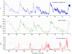
The physical properties of the ice and of material trapped in it can be used to reconstruct the climate over the age range of the core. The proportions of different oxygen and hydrogen isotopes provide information about ancient temperatures, and the air trapped in tiny bubbles can be analysed to determine the level of atmospheric gases such as carbon dioxide. Since heat flow in a large ice sheet is very slow, the borehole temperature is another indicator of temperature in the past. These data can be combined to find the climate model that best fits all the available data.
Impurities in ice cores may depend on location. Coastal areas are more likely to include material of marine origin, such as sea salt ions. Greenland ice cores contain layers of wind-blown dust that correlate with cold, dry periods in the past, when cold deserts were scoured by wind. Radioactive elements, either of natural origin or created by nuclear testing, can be used to date the layers of ice. Some volcanic events that were sufficiently powerful to send material around the globe have left a signature in many different cores that can be used to synchronise their time scales.
Ice cores have been studied since the early 20th century, and several cores were drilled as a result of the International Geophysical Year (1957–1958). Depths of over 400 m were reached, a record which was extended in the 1960s to 2164 m at Byrd Station in Antarctica. Soviet ice drilling projects in Antarctica include decades of work at Vostok Station, with the deepest core reaching 3769 m. Numerous other deep cores in the Antarctic have been completed over the years, including the West Antarctic Ice Sheet project, and cores managed by the British Antarctic Survey and the International Trans-Antarctic Scientific Expedition. In Greenland, a sequence of collaborative projects began in the 1970s with the Greenland Ice Sheet Project; there have been multiple follow-up projects, with the most recent, the East Greenland Ice-Core Project, originally expected to complete a deep core in east Greenland in 2020 but since postponed.[1]
Structure of ice sheets and cores
An ice core is a vertical column through a glacier, sampling the layers that formed through an annual cycle of snowfall and melt.[2] As snow accumulates, each layer presses on lower layers, making them denser until they turn into firn. Firn is not dense enough to prevent air from escaping; but at a density of about 830 kg/m3 it turns to ice, and the air within is sealed into bubbles that capture the composition of the atmosphere at the time the ice formed.[3] The depth at which this occurs varies with location, but in Greenland and the Antarctic it ranges from 64 m to 115 m.[4] Because the rate of snowfall varies from site to site, the age of the firn when it turns to ice varies a great deal. At Summit Camp in Greenland, the depth is 77 m and the ice is 230 years old; at Dome C in Antarctica the depth is 95 m and the age 2500 years.[5] As further layers build up, the pressure increases, and at about 1500 m the crystal structure of the ice changes from hexagonal to cubic, allowing air molecules to move into the cubic crystals and form a clathrate. The bubbles disappear and the ice becomes more transparent.[3]
Two or three feet of snow may turn into less than a foot of ice.[3] The weight above makes deeper layers of ice thin and flow outwards. Ice is lost at the edges of the glacier to icebergs, or to summer melting, and the overall shape of the glacier does not change much with time.[6] The outward flow can distort the layers, so it is desirable to drill deep ice cores at places where there is very little flow. These can be located using maps of the flow lines.[7]
Impurities in the ice provide information on the environment from when they were deposited. These include soot, ash, and other types of particle from forest fires and volcanoes; isotopes such as beryllium-10 created by cosmic rays; micrometeorites; and pollen.[2] The lowest layer of a glacier, called basal ice, is frequently formed of subglacial meltwater that has refrozen. It can be up to about 20 m thick, and though it has scientific value (for example, it may contain subglacial microbial populations),[8] it often does not retain stratigraphic information.[9]
Cores are often drilled in areas such as Antarctica and central Greenland where the temperature is almost never warm enough to cause melting, but the summer sun can still alter the snow. In polar areas, the sun is visible day and night during the local summer and invisible all winter. It can make some snow sublimate, leaving the top inch or so less dense. When the sun approaches its lowest point in the sky, the temperature drops and hoar frost forms on the top layer. Buried under the snow of following years, the coarse-grained hoar frost compresses into lighter layers than the winter snow. As a result, alternating bands of lighter and darker ice can be seen in an ice core.[10]
Coring
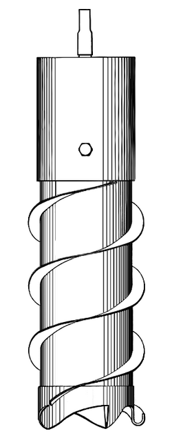
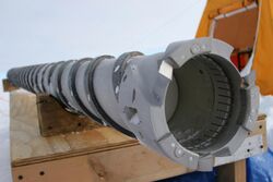
Ice cores are collected by cutting around a cylinder of ice in a way that enables it to be brought to the surface. Early cores were often collected with hand augers and they are still used for short holes. A design for ice core augers was patented in 1932 and they have changed little since. An auger is essentially a cylinder with helical metal ribs (known as flights) wrapped around the outside, at the lower end of which are cutting blades. Hand augers can be rotated by a T handle or a brace handle, and some can be attached to handheld electric drills to power the rotation. With the aid of a tripod for lowering and raising the auger, cores up to 50 m deep can be retrieved, but the practical limit is about 30 m for engine-powered augers, and less for hand augers. Below this depth, electromechanical or thermal drills are used.[11]
The cutting apparatus of a drill is on the bottom end of a drill barrel, the tube that surrounds the core as the drill cuts downward. The cuttings (chips of ice cut away by the drill) must be drawn up the hole and disposed of or they will reduce the cutting efficiency of the drill.[12] They can be removed by compacting them into the walls of the hole or into the core, by air circulation (dry drilling),[12][13] or by the use of a drilling fluid (wet drilling).[14] Dry drilling is limited to about 400 m depth, since below that point a hole would close up as the ice deforms from the weight of the ice above.[15]
Drilling fluids are chosen to balance the pressure so that the hole remains stable.[13] The fluid must have a low kinematic viscosity to reduce tripping time (the time taken to pull the drilling equipment out of the hole and return it to the bottom of the hole). Since retrieval of each segment of core requires tripping, a slower speed of travel through the drilling fluid could add significant time to a project—a year or more for a deep hole. The fluid must contaminate the ice as little as possible; it must have low toxicity, for safety and to minimize the effect on the environment; it must be available at a reasonable cost; and it must be relatively easy to transport.[16] Historically, there have been three main types of ice drilling fluids: two-component fluids based on kerosene-like products mixed with fluorocarbons to increase density; alcohol compounds, including aqueous ethylene glycol and ethanol solutions; and esters, including n-butyl acetate. Newer fluids have been proposed, including new ester-based fluids, low-molecular weight dimethyl siloxane oils, fatty-acid esters, and kerosene-based fluids mixed with foam-expansion agents.[17]
Rotary drilling is the main method of drilling for minerals and it has also been used for ice drilling. It uses a string of drill pipe rotated from the top, and drilling fluid is pumped down through the pipe and back up around it. The cuttings are removed from the fluid at the top of the hole and the fluid is then pumped back down.[14] This approach requires long trip times, since the entire drill string must be hoisted out of the hole, and each length of pipe must be separately disconnected, and then reconnected when the drill string is reinserted.[12][18] Along with the logistical difficulties associated with bringing heavy equipment to ice sheets, this makes traditional rotary drills unattractive.[12] In contrast, wireline drills allow the removal of the core barrel from the drill assembly while it is still at the bottom of the borehole. The core barrel is hoisted to the surface, and the core removed; the barrel is lowered again and reconnected to the drill assembly.[19] Another alternative is flexible drill-stem rigs, in which the drill string is flexible enough to be coiled when at the surface. This eliminates the need to disconnect and reconnect the pipes during a trip.[18]
The need for a string of drillpipe that extends from the surface to the bottom of the borehole can be eliminated by suspending the entire downhole assembly on an armoured cable that conveys power to the downhole motor. These cable-suspended drills can be used for both shallow and deep holes; they require an anti-torque device, such as leaf-springs that press against the borehole, to prevent the drill assembly rotating around the drillhead as it cuts the core.[20] The drilling fluid is usually circulated down around the outside of the drill and back up between the core and core barrel; the cuttings are stored in the downhole assembly, in a chamber above the core. When the core is retrieved, the cuttings chamber is emptied for the next run. Some drills have been designed to retrieve a second annular core outside the central core, and in these drills the space between the two cores can be used for circulation. Cable-suspended drills have proved to be the most reliable design for deep ice drilling.[21][22]
Thermal drills, which cut ice by electrically heating the drill head, can also be used, but they have some disadvantages. Some have been designed for working in cold ice; they have high power consumption and the heat they produce can degrade the quality of the retrieved ice core. Early thermal drills, designed for use without drilling fluid, were limited in depth as a result; later versions were modified to work in fluid-filled holes but this slowed down trip times, and these drills retained the problems of the earlier models. In addition, thermal drills are typically bulky and can be impractical to use in areas where there are logistical difficulties. More recent modifications include the use of antifreeze, which eliminates the need for heating the drill assembly and hence reduces the power needs of the drill.[23] Hot-water drills use jets of hot water at the drill head to melt the water around the core. The drawbacks are that it is difficult to accurately control the dimensions of the borehole, the core cannot easily be kept sterile, and the heat may cause thermal shock to the core.[24]
When drilling in temperate ice, thermal drills have an advantage over electromechanical (EM) drills: ice melted by pressure can refreeze on EM drill bits, reducing cutting efficiency, and can clog other parts of the mechanism. EM drills are also more likely to fracture ice cores where the ice is under high stress.[25]
When drilling deep holes, which require drilling fluid, the hole must be cased (fitted with a cylindrical lining), since otherwise the drilling fluid will be absorbed by the snow and firn. The casing has to reach down to the impermeable ice layers. To install casing a shallow auger can be used to create a pilot hole, which is then reamed (expanded) until it is wide enough to accept the casing; a large diameter auger can also be used, avoiding the need for reaming. An alternative to casing is to use water in the borehole to saturate the porous snow and firn; the water eventually turns to ice.[4]
Ice cores from different depths are not all equally in demand by scientific investigators, which can lead to a shortage of ice cores at certain depths. To address this, work has been done on technology to drill replicate cores: additional cores, retrieved by drilling into the sidewall of the borehole, at depths of particular interest. Replicate cores were successfully retrieved at WAIS divide in the 2012–2013 drilling season, at four different depths.[26]
Large coring projects
The logistics of any coring project are complex because the locations are usually difficult to reach, and may be at high altitude. The largest projects require years of planning and years to execute, and are usually run as international consortiums. The EastGRIP project, for example, which as of 2017 is drilling in eastern Greenland, is run by the Centre for Ice and Climate (Niels Bohr Institute, University of Copenhagen) in Denmark ,[27] and includes representatives from 12 countries on its steering committee.[28] Over the course of a drilling season, scores of people work at the camp,[29] and logistics support includes airlift capabilities provided by the US Air National Guard, using Hercules transport planes owned by the National Science Foundation.[30] In 2015 the EastGRIP team moved the camp facilities from NEEM, a previous Greenland ice core drilling site, to the EastGRIP site.[31] Drilling is expected to continue until at least 2020.[32]
Core processing
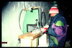
With some variation between projects, the following steps must occur between drilling and final storage of the ice core.[33]
The drill removes an annulus of ice around the core but does not cut under it. A spring-loaded lever arm called a core dog can break off the core and hold it in place while it is brought to the surface. The core is then extracted from the drill barrel, usually by laying it out flat so that the core can slide out onto a prepared surface.[33] The core must be cleaned of drilling fluid as it is slid out; for the WAIS Divide coring project, a vacuuming system was set up to facilitate this. The surface that receives the core should be aligned as accurately as possible with the drill barrel to minimise mechanical stress on the core, which can easily break. The ambient temperature is kept well below freezing to avoid thermal shock.[34]
A log is kept with information about the core, including its length and the depth it was retrieved from, and the core may be marked to show its orientation. It is usually cut into shorter sections, the standard length in the US being one metre. The cores are then stored on site, usually in a space below snow level to simplify temperature maintenance, though additional refrigeration can be used. If more drilling fluid must be removed, air may be blown over the cores. Any samples needed for preliminary analysis are taken. The core is then bagged, often in polythene, and stored for shipment. Additional packing, including padding material, is added. When the cores are flown from the drilling site, the aircraft's flight deck is unheated to help maintain a low temperature; when they are transported by ship they must be kept in a refrigeration unit.[34]
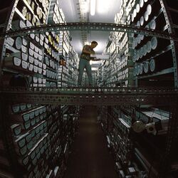
There are several locations around the world that store ice cores, such as the National Ice Core Laboratory in the US. These locations make samples available for testing. A substantial fraction of each core is archived for future analyses.[34][35]
Brittle ice
Over a depth range known as the brittle ice zone, bubbles of air are trapped in the ice under great pressure. When the core is brought to the surface, the bubbles can exert a stress that exceeds the tensile strength of the ice, resulting in cracks and spall.[36] At greater depths, the air disappears into clathrates and the ice becomes stable again.[36][37] At the WAIS Divide site, the brittle ice zone was from 520 m to 1340 m depth.[36]
The brittle ice zone typically returns poorer quality samples than for the rest of the core. Some steps can be taken to alleviate the problem. Liners can be placed inside the drill barrel to enclose the core before it is brought to the surface, but this makes it difficult to clean off the drilling fluid. In mineral drilling, special machinery can bring core samples to the surface at bottom-hole pressure, but this is too expensive for the inaccessible locations of most drilling sites. Keeping the processing facilities at very low temperatures limits thermal shocks. Cores are most brittle at the surface, so another approach is to break them into 1 m lengths in the hole. Extruding the core from the drill barrel into a net helps keep it together if it shatters. Brittle cores are also often allowed to rest in storage at the drill site for some time, up to a full year between drilling seasons, to let the ice gradually relax.[36][38]
Ice core data
Dating
Many different kinds of analysis are performed on ice cores, including visual layer counting, tests for electrical conductivity and physical properties, and assays for inclusion of gases, particles, radionuclides, and various molecular species. For the results of these tests to be useful in the reconstruction of palaeoenvironments, there has to be a way to determine the relationship between depth and age of the ice. The simplest approach is to count layers of ice that correspond to the original annual layers of snow, but this is not always possible. An alternative is to model the ice accumulation and flow to predict how long it takes a given snowfall to reach a particular depth. Another method is to correlate radionuclides or trace atmospheric gases with other timescales such as periodicities in the earth's orbital parameters.[39]
A difficulty in ice core dating is that gases can diffuse through firn, so the ice at a given depth may be substantially older than the gases trapped in it. As a result, there are two chronologies for a given ice core: one for the ice, and one for the trapped gases. To determine the relationship between the two, models have been developed for the depth at which gases are trapped for a given location, but their predictions have not always proved reliable.[40][41] At locations with very low snowfall, such as Vostok, the uncertainty in the difference between ages of ice and gas can be over 1,000 years.[42]
The density and size of the bubbles trapped in ice provide an indication of crystal size at the time they formed. The size of a crystal is related to its growth rate, which in turn depends on the temperature, so the properties of the bubbles can be combined with information on accumulation rates and firn density to calculate the temperature when the firn formed.[43]
Radiocarbon dating can be used on the carbon in trapped CO2. In the polar ice sheets there is about 15–20 µg of carbon in the form of CO2 in each kilogram of ice, and there may also be carbonate particles from wind-blown dust (loess). The CO2 can be isolated by subliming the ice in a vacuum, keeping the temperature low enough to avoid the loess giving up any carbon. The results have to be corrected for the presence of 14C produced directly in the ice by cosmic rays, and the amount of correction depends strongly on the location of the ice core. Corrections for 14C produced by nuclear testing have much less impact on the results.[44] Carbon in particulates can also be dated by separating and testing the water-insoluble organic components of dust. The very small quantities typically found require at least 300 g of ice to be used, limiting the ability of the technique to precisely assign an age to core depths.[45]
Timescales for ice cores from the same hemisphere can usually be synchronised using layers that include material from volcanic events. It is more difficult to connect the timescales in different hemispheres. The Laschamp event, a geomagnetic reversal about 40,000 years ago, can be identified in cores;[46][47] away from that point, measurements of gases such as CH4 (methane) can be used to connect the chronology of a Greenland core (for example) with an Antarctic core.[48][49] In cases where volcanic tephra is interspersed with ice, it can be dated using argon/argon dating and hence provide fixed points for dating the ice.[50][51] Uranium decay has also been used to date ice cores.[50][52] Another approach is to use Bayesian probability techniques to find the optimal combination of multiple independent records. This approach was developed in 2010 and has since been turned into a software tool, DatIce.[53][54]
The boundary between the Pleistocene and the Holocene, about 11,700 years ago, is now formally defined with reference to data on Greenland ice cores. Formal definitions of stratigraphic boundaries allow scientists in different locations to correlate their findings. These often involve fossil records, which are not present in ice cores, but cores have extremely precise palaeoclimatic information that can be correlated with other climate proxies.[55]
The dating of ice sheets has proved to be a key element in providing dates for palaeoclimatic records. According to Richard Alley, "In many ways, ice cores are the 'rosetta stones' that allow development of a global network of accurately dated paleoclimatic records using the best ages determined anywhere on the planet".[43]
Visual analysis
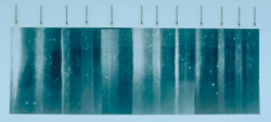
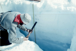
Cores show visible layers, which correspond to annual snowfall at the core site. If a pair of pits is dug in fresh snow with a thin wall between them and one of the pits is roofed over, an observer in the roofed pit will see the layers revealed by sunlight shining through. A six-foot pit may show anything from less than a year of snow to several years of snow, depending on the location. Poles left in the snow from year to year show the amount of accumulated snow each year, and this can be used to verify that the visible layer in a snow pit corresponds to a single year's snowfall.[57]
In central Greenland a typical year might produce two or three feet of winter snow, plus a few inches of summer snow. When this turns to ice, the two layers will make up no more than a foot of ice. The layers corresponding to the summer snow will contain bigger bubbles than the winter layers, so the alternating layers remain visible, which makes it possible to count down a core and determine the age of each layer.[58] As the depth increases to the point where the ice structure changes to a clathrate, the bubbles are no longer visible, and the layers can no longer be seen. Dust layers may now become visible. Ice from Greenland cores contains dust carried by wind; the dust appears most strongly in late winter, and appears as cloudy grey layers. These layers are stronger and easier to see at times in the past when the earth's climate was cold, dry, and windy.[59]
Any method of counting layers eventually runs into difficulties as the flow of the ice causes the layers to become thinner and harder to see with increasing depth.[60] The problem is more acute at locations where accumulation is high; low accumulation sites, such as central Antarctica, must be dated by other methods.[61] For example, at Vostok, layer counting is only possible down to an age of 55,000 years.[62]
When there is summer melting, the melted snow refreezes lower in the snow and firn, and the resulting layer of ice has very few bubbles so is easy to recognise in a visual examination of a core. Identification of these layers, both visually and by measuring density of the core against depth, allows the calculation of a melt-feature percentage (MF): an MF of 100% would mean that every year's deposit of snow showed evidence of melting. MF calculations are averaged over multiple sites or long time periods in order to smooth the data. Plots of MF data over time reveal variations in the climate, and have shown that since the late 20th century melting rates have been increasing.[63][64]
In addition to manual inspection and logging of features identified in a visual inspection, cores can be optically scanned so that a digital visual record is available. This requires the core to be cut lengthwise, so that a flat surface is created.[65]
Isotopic analysis
The isotopic composition of the oxygen in a core can be used to model the temperature history of the ice sheet. Oxygen has three stable isotopes, 16O, 17O and 18O.[66] The ratio between 18O and 16O indicates the temperature when the snow fell.[67] Because 16O is lighter than 18O, water containing 16O is slightly more likely to turn into vapour, and water containing 18O is slightly more likely to condense from vapour into rain or snow crystals. At lower temperatures, the difference is more pronounced. The standard method of recording the 18O/16O ratio is to subtract the ratio in a standard known as standard mean ocean water (SMOW):[67]
[math]\displaystyle{ \mathrm{\delta ^{18}O} = \Biggl( \mathrm{\frac{\bigl( \frac{^{18}O}{^{16}O} \bigr)_{sample}}{\bigl( \frac{^{18}O}{^{16}O} \bigr)_{SMOW}}} -1 \Biggr) \times 1000\ ^{o}\!/\!_{oo}, }[/math]
where the ‰ sign indicates parts per thousand.[67] A sample with the same 18O/16O ratio as SMOW has a δ18O of 0‰; a sample that is depleted in 18O has a negative δ18O.[67] Combining the δ18O measurements of an ice core sample with the borehole temperature at the depth it came from provides additional information, in some cases leading to significant corrections to the temperatures deduced from the δ18O data.[68][69] Not all boreholes can be used in these analyses. If the site has experienced significant melting in the past, the borehole will no longer preserve an accurate temperature record.[70]
Hydrogen ratios can also be used to calculate a temperature history. Deuterium (2H, or D) is heavier than hydrogen (1H) and makes water more likely to condense and less likely to evaporate. A δD ratio can be defined in the same way as δ18O.[71][72] There is a linear relationship between δ18O and δD:[73]
[math]\displaystyle{ \mathrm{\delta D} = 8 \times \mathrm{\delta ^{18} O} + \mathrm{d}, }[/math]
where d is the deuterium excess. It was once thought that this meant it was unnecessary to measure both ratios in a given core, but in 1979 Merlivat and Jouzel showed that the deuterium excess reflects the temperature, relative humidity, and wind speed of the ocean where the moisture originated. Since then it has been customary to measure both.[73]
Water isotope records, analyzed in cores from Camp Century and Dye 3 in Greenland, were instrumental in the discovery of Dansgaard-Oeschger events—rapid warming at the onset of an interglacial, followed by slower cooling.[74] Other isotopic ratios have been studied, for example, the ratio between 13C and 12C can provide information about past changes in the carbon cycle. Combining this information with records of carbon dioxide levels, also obtained from ice cores, provides information about the mechanisms behind changes in CO2 over time.[75]
Palaeoatmospheric sampling
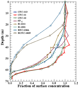
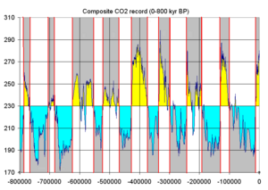
It was understood in the 1960s that analyzing the air trapped in ice cores would provide useful information on the paleoatmosphere, but it was not until the late 1970s that a reliable extraction method was developed. Early results included a demonstration that the CO2 concentration was 30% less at the last glacial maximum than just before the start of the industrial age. Further research has demonstrated a reliable correlation between CO2 levels and the temperature calculated from ice isotope data.[77]
Because CH4 (methane) is produced in lakes and wetlands, the amount in the atmosphere is correlated with the strength of monsoons, which are in turn correlated with the strength of low-latitude summer insolation. Since insolation depends on orbital cycles, for which a timescale is available from other sources, CH4 can be used to determine the relationship between core depth and age.[61][62] N2O (nitrous oxide) levels are also correlated with glacial cycles, though at low temperatures the graph differs somewhat from the CO2 and CH4 graphs.[77][78] Similarly, the ratio between N2 (nitrogen) and O2 (oxygen) can be used to date ice cores: as air is gradually trapped by the snow turning to firn and then ice, O2 is lost more easily than N2, and the relative amount of O2 correlates with the strength of local summer insolation. This means that the trapped air retains, in the ratio of O2 to N2, a record of the summer insolation, and hence combining this data with orbital cycle data establishes an ice core dating scheme.[61][79]
Diffusion within the firn layer causes other changes that can be measured. Gravity causes heavier molecules to be enriched at the bottom of a gas column, with the amount of enrichment depending on the difference in mass between the molecules. Colder temperatures cause heavier molecules to be more enriched at the bottom of a column. These fractionation processes in trapped air, determined by the measurement of the 15N/14N ratio and of neon, krypton and xenon, have been used to infer the thickness of the firn layer, and determine other palaeoclimatic information such as past mean ocean temperatures.[69] Some gases such as helium can rapidly diffuse through ice, so it may be necessary to test for these "fugitive gases" within minutes of the core being retrieved to obtain accurate data.[34] Chlorofluorocarbons (CFCs), which contribute to the greenhouse effect and also cause ozone loss in the stratosphere,[80] can be detected in ice cores after about 1950; almost all CFCs in the atmosphere were created by human activity.[80][81]
Greenland cores, during times of climatic transition, may show excess CO
2 in air bubbles when analysed, due to CO
2 production by acidic and alkaline impurities.[82]
Glaciochemistry
Summer snow in Greenland contains some sea salt, blown from the surrounding waters; there is less of it in winter, when much of the sea surface is covered by pack ice. Similarly, hydrogen peroxide appears only in summer snow because its production in the atmosphere requires sunlight. These seasonal changes can be detected because they lead to changes in the electrical conductivity of the ice. Placing two electrodes with a high voltage between them on the surface of the ice core gives a measurement of the conductivity at that point. Dragging them down the length of the core, and recording the conductivity at each point, gives a graph that shows an annual periodicity. Such graphs also identify chemical changes caused by non-seasonal events such as forest fires and major volcanic eruptions. When a known volcanic event, such as the eruption of Laki in Iceland in 1783, can be identified in the ice core record, it provides a cross-check on the age determined by layer counting.[83] Material from Laki can be identified in Greenland ice cores, but did not spread as far as Antarctica; the 1815 eruption of Tambora in Indonesia injected material into the stratosphere, and can be identified in both Greenland and Antarctic ice cores. If the date of the eruption is not known, but it can be identified in multiple cores, then dating the ice can in turn give a date for the eruption, which can then be used as a reference layer.[84] This was done, for example, in an analysis of the climate for the period from 535 to 550 AD, which was thought to be influenced by an otherwise unknown tropical eruption in about 533 AD; but which turned out to be caused by two eruptions, one in 535 or early 536 AD, and a second one in 539 or 540 AD.[85] There are also more ancient reference points, such as the eruption of Toba about 72,000 years ago.[84]
Many other elements and molecules have been detected in ice cores.[86] In 1969, it was discovered that lead levels in Greenland ice had increased by a factor of over 200 since pre-industrial times, and increases in other elements produced by industrial processes, such as copper, cadmium, and zinc, have also been recorded.[87] The presence of nitric and sulfuric acid (HNO3 and H2SO4) in precipitation can be shown to correlate with increasing fuel combustion over time. Methanesulfonate (MSA) (CH3SO−3) is produced in the atmosphere by marine organisms, so ice core records of MSA provide information on the history of the oceanic environment. Both hydrogen peroxide (H2O2) and formaldehyde (HCHO) have been studied, along with organic molecules such as carbon black that are linked to vegetation emissions and forest fires.[86] Some species, such as calcium and ammonium, show strong seasonal variation. In some cases there are contributions from more than one source to a given species: for example, Ca++ comes from dust as well as from marine sources; the marine input is much greater than the dust input and so although the two sources peak at different times of the year, the overall signal shows a peak in the winter, when the marine input is at a maximum.[88] Seasonal signals can be erased at sites where the accumulation is low, by surface winds; in these cases it is not possible to date individual layers of ice between two reference layers.[89]
Some of the deposited chemical species may interact with the ice, so what is detected in an ice core is not necessarily what was originally deposited. Examples include HCHO and H2O2. Another complication is that in areas with low accumulation rates, deposition from fog can increase the concentration in the snow, sometimes to the point where the atmospheric concentration could be overestimated by a factor of two.[90]
| Source | Via | Measured in polar ice |
|---|---|---|
| Oceans | Waves and wind | Sea salt: Na+, Cl−, Mg2+, Ca2+, SO2−4, K+ |
| Land | Aridity and wind | Terrestrial salts: Mg2+, Ca2+, CO2−3, SO2−4, aluminosilicates |
| Human and biological gas emissions: SO2, (CH3)2S, H2S, COS, NOx, NH3, hydrocarbons and halocarbons | Atmospheric chemistry: O3, H2O2, OH, RO2, NO3, | H+, NH+4, Cl−, NO−3, SO2−4, CH3SO−3, F−, HCOO−, other organic compounds |
Radionuclides
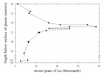
Galactic cosmic rays produce 10Be in the atmosphere at a rate that depends on the solar magnetic field. The strength of the field is related to the intensity of solar radiation, so the level of 10Be in the atmosphere is a proxy for climate. Accelerator mass spectrometry can detect the low levels of 10Be in ice cores, about 10,000 atoms in a gram of ice, and these can be used to provide long-term records of solar activity.[92] Tritium (3H), created by nuclear weapons testing in the 1950s and 1960s, has been identified in ice cores,[93] and both 36Cl and 239Pu have been found in ice cores in Antarctica and Greenland.[94][95][96] Chlorine-36, which has a half-life of 301,000 years, has been used to date cores, as have krypton (85Kr, with a half-life of 11 years), lead (210Pb, 22 years), and silicon (32Si, 172 years).[89]
Other inclusions
Meteorites and micrometeorites that land on polar ice are sometimes concentrated by local environmental processes. For example, there are places in Antarctica where winds evaporate surface ice, concentrating the solids that are left behind, including meteorites. Meltwater ponds can also contain meteorites. At the South Pole Station, ice in a well is melted to provide a water supply, leaving micrometeorites behind. These have been collected by a robotic "vacuum cleaner" and examined, leading to improved estimates of their flux and mass distribution.[97] The well is not an ice core, but the age of the ice that was melted is known, so the age of the recovered particles can be determined. The well becomes about 10 m deeper each year, so micrometeorites collected in a given year are about 100 years older than those from the previous year.[98] Pollen, an important component of sediment cores, can also be found in ice cores. It provides information on changes in vegetation.[99]
Physical properties
In addition to the impurities in a core and the isotopic composition of the water, the physical properties of the ice are examined. Features such as crystal size and axis orientation can reveal the history of ice flow patterns in the ice sheet. The crystal size can also be used to determine dates, though only in shallow cores.[100]
History
Early years
In 1841 and 1842, Louis Agassiz drilled holes in the Unteraargletscher in the Alps; these were drilled with iron rods and did not produce cores. The deepest hole achieved was 60 m. On Erich von Drygalski's Antarctic expedition in 1902 and 1903, 30 m holes were drilled in an iceberg south of the Kerguelen Islands and temperature readings were taken. The first scientist to create a snow sampling tool was James E. Church, described by Pavel Talalay as "the father of modern snow surveying". In the winter of 1908–1909, Church constructed steel tubes with slots and cutting heads to retrieve cores of snow up to 3 m long. Similar devices are in use today, modified to allow sampling to a depth of about 9 m. They are simply pushed into the snow and rotated by hand.[101]
The first systematic study of snow and firn layers was by Ernst Sorge, who was part of the Alfred Wegener Expedition to central Greenland in 1930–1931. Sorge dug a 15 m pit to examine the snow layers, and his results were later formalized into Sorge's Law of Densification by Henri Bader, who went on to do additional coring work in northwest Greenland in 1933.[102] In the early 1950s, a SIPRE expedition took pit samples over much of the Greenland ice sheet, obtaining early oxygen isotope ratio data. Three other expeditions in the 1950s began ice coring work: a joint Norwegian-British-Swedish Antarctic Expedition (NBSAE), in Queen Maud Land in Antarctica; the Juneau Ice Field Research Project (JIRP), in Alaska; and Expéditions Polaires Françaises, in central Greenland. Core quality was poor, but some scientific work was done on the retrieved ice.[103]
The International Geophysical Year (1957–1958) saw increased glaciology research around the world, with one of the high priority research targets being deep cores in polar regions. SIPRE conducted pilot drilling trials in 1956 (to 305 m) and 1957 (to 411 m) at Site 2 in Greenland; the second core, with the benefit of the previous year's drilling experience, was retrieved in much better condition, with fewer gaps.[104] In Antarctica, a 307 m core was drilled at Byrd Station in 1957–1958, and a 264 m core at Little America V, on the Ross Ice Shelf, the following year.[105] The success of the IGY core drilling led to increased interest in improving ice coring capabilities, and was followed by a CRREL project at Camp Century, where in the early 1960s three holes were drilled, the deepest reaching the base of the ice sheet at 1387 m in July 1966.[106] The drill used at Camp Century then went to Byrd Station, where a 2164 m hole was drilled to bedrock before the drill was frozen into the borehole by sub-ice meltwater and had to be abandoned.[107]
French, Australian and Canadian projects from the 1960s and 1970s include a 905 m core at Dome C in Antarctica, drilled by CNRS; cores at Law Dome drilled by ANARE, starting in 1969 with a 382 m core; and Devon Ice Cap cores recovered by a Canadian team in the 1970s.[108]
Antarctica deep cores
Soviet ice drilling projects began in the 1950s, in Franz Josef Land, the Urals, Novaya Zemlya, and at Mirny and Vostok in the Antarctic; not all these early holes retrieved cores.[109] Over the following decades work continued at multiple locations in Asia.[110] Drilling in the Antarctic focused mostly on Mirny and Vostok, with a series of deep holes at Vostok begun in 1970.[111] The first deep hole at Vostok reached 506.9 m in April 1970; by 1973 a depth of 952 m had been reached. A subsequent hole, Vostok 2, drilled from 1971 to 1976, reached 450 m, and Vostok 3 reached 2202 m in 1985 after six drilling seasons.[112] Vostok 3 was the first core to retrieve ice from the previous glacial period, 150,000 years ago.[113] Drilling was interrupted by a fire at the camp in 1982, but further drilling began in 1984, eventually reaching 2546 m in 1989. A fifth Vostok core was begun in 1990, reached 3661 m in 2007, and was later extended to 3769 m.[108][113] The estimated age of the ice is 420,000 years at 3310 m depth; below that point it is difficult to interpret the data reliably because of mixing of the ice.[114]
EPICA, a European ice coring collaboration, was formed in the 1990s, and two holes were drilled in East Antarctica: one at Dome C, which reached 2871 m in only two seasons of drilling, but which took another four years to reach bedrock at 3260 m; and one at Kohnen Station, which reached bedrock at 2760 m in 2006. The Dome C core had very low accumulation rates, which mean that the climate record extended a long way; by the end of the project the usable data extended to 800,000 years ago.[114]
Other deep Antarctic cores included a Japanese project at Dome F, which reached 2503 m in 1996, with an estimated age of 330,000 years for the bottom of the core; and a subsequent hole at the same site which reached 3035 m in 2006, estimated to reach ice 720,000 years old.[114] US teams drilled at McMurdo Station in the 1990s, and at Taylor Dome (554 m in 1994) and Siple Dome (1004 m in 1999), with both cores reaching ice from the last glacial period.[114][115] The West Antarctic Ice Sheet (WAIS) project, completed in 2011, reached 3405 m; the site has high snow accumulation so the ice only extends back 62,000 years, but as a consequence, the core provides high resolution data for the period it covers.[61] A 948 m core was drilled at Berkner Island by a project managed by the British Antarctic Survey from 2002 to 2005, extending into the last glacial period;[61] and an Italian-managed ITASE project completed a 1620 m core at Talos Dome in 2007.[61][116]
In 2016, cores were retrieved from the Allan Hills in Antarctica in an area where old ice lay near the surface. The cores were dated by potassium-argon dating; traditional ice core dating is not possible as not all layers were present. The oldest core was found to include ice from 2.7 million years ago—by far the oldest ice yet dated from a core.[117]
Greenland deep cores
In 1970, scientific discussions began which resulted in the Greenland Ice Sheet Project (GISP), a multinational investigation into the Greenland ice sheet that lasted until 1981. Years of field work were required to determine the ideal location for a deep core; the field work included several intermediate-depth cores, at Dye 3 (372 m in 1971), Milcent (398 m in 1973) and Crete (405 m in 1974), among others. A location in north-central Greenland was selected as ideal, but financial constraints forced the group to drill at Dye 3 instead, beginning in 1979. The hole reached bedrock at 2037 m, in 1981. Two holes, 30 km apart, were eventually drilled at the north-central location in the early 1990s by two groups: GRIP, a European consortium, and GISP-2, a group of US universities. GRIP reached bedrock at 3029 m in 1992, and GISP-2 reached bedrock at 3053 m the following year.[118] Both cores were limited to about 100,000 years of climatic information, and since this was thought to be connected to the topography of the rock underlying the ice sheet at the drill sites, a new site was selected 200 km north of GRIP, and a new project, NorthGRIP, was launched as an international consortium led by Denmark. Drilling began in 1996; the first hole had to be abandoned at 1400 m in 1997, and a new hole was begun in 1999, reaching 3085 m in 2003. The hole did not reach bedrock, but terminated at a subglacial river. The core provided climatic data back to 123,000 years ago, which covered part of the last interglacial period. The subsequent North Greenland Eemian (NEEM) project retrieved a 2537 m core in 2010 from a site further north, extending the climatic record to 128,500 years ago;[113] NEEM was followed by EastGRIP, which began in 2015 in east Greenland and was planned to be completed in 2020.[119] In March 2020, the 2020 EGRIP field campaign was cancelled due to the ongoing COVID-19 pandemic. EastGRIP reopened for field work in 2022, where the CryoEgg reached new depths in the ice, under pressures in excess of 200 bar and temperatures of around -30c.[120][121]
Non-polar cores
Ice cores have been drilled at locations away from the poles, notably in the Himalayas and the Andes. Some of these cores reach back to the last glacial period, but they are more important as records of El Niño events and of monsoon seasons in south Asia.[61] Cores have also been drilled on Mount Kilimanjaro,[61] in the Alps,[61] and in Indonesia,[122] New Zealand,[123] Iceland,[124] Scandinavia,[125] Canada,[126] and the US.[127]
Future plans
IPICS (International Partnerships in Ice Core Sciences) has produced a series of white papers outlining future challenges and scientific goals for the ice core science community. These include plans to:[128]
- Retrieve ice cores that reach back over 1.2 million years, in order to obtain multiple iterations of ice core record for the 40,000-year long climate cycles known to have operated at that time. Current cores reach back over 800,000 years, and show 100,000-year cycles.
- Improve ice core chronologies, including connecting chronologies of multiple cores.
- Identify additional proxies from ice cores, for example for sea ice, marine biological productivity, or forest fires.
- Drill additional cores to provide high-resolution data for the last 2,000 years, to use as input for detailed climate modelling.
- Identify an improved drilling fluid
- Improve the ability to handle brittle ice, both while drilling and in transport and storage
- Find a way to handle cores which have pressurised water at bedrock
- Come up with a standardised lightweight drill capable of drilling both wet and dry holes, and able to reach depths of up to 1000 m.
- Improve core handling to maximise the information that can be obtained from each core.
See also
References
- ↑ Berwyn, Bob (27 March 2020). "Coronavirus Already Hindering Climate Science, But the Worst Disruptions Are Likely Yet to Come". https://insideclimatenews.org/news/26032020/coronavirus-climate-science-research-impact.
- ↑ 2.0 2.1 Alley 2000, pp. 71–73.
- ↑ 3.0 3.1 3.2 Alley 2000, pp. 48–50.
- ↑ 4.0 4.1 Talalay 2016, p. 263.
- ↑ Bradley, Raymond S. (2015). Paleoclimatology: Reconstructing Climates of the Quaternary. Amsterdam: Academic Press. p. 138. ISBN 978-0-12-386913-5.
- ↑ Alley 2000, pp. 35–36.
- ↑ Knight, Peter G. (1999). Glaciers. Cheltenham, UK: Stanley Thornes. p. 206. ISBN 978-0-7487-4000-0. https://archive.org/details/glaciers0000knig/page/206.
- ↑ Tulaczyk, S.; Elliot, D.; Vogel, S.W.; Powell, R.D.; Priscu, J.C.; Clow, G.D. (2002). FASTDRILL: Interdisciplinary Polar Research Based on Fast Ice-Sheet Drilling (Report). 2002 FASTDRILL Workshop. p. 9. https://websites.pmc.ucsc.edu/~tulaczyk/Report_I_V.pdf.
- ↑ Gabrielli, Paolo; Vallelonga, Paul (2015). "Contaminant Records in Ice Cores". in Blais, Jules M.. Environmental Contaminants: Using Natural Archives to Track Sources and Long-Term Trends of Pollution. Dordrecht, Netherlands: Springer. p. 395. ISBN 978-94-017-9540-1.
- ↑ Alley 2000, pp. 43–46.
- ↑ 11.0 11.1 Talalay 2016, pp. 34–35.
- ↑ 12.0 12.1 12.2 12.3 Talalay 2016, p. 59.
- ↑ 13.0 13.1 Talalay 2016, p. 7.
- ↑ 14.0 14.1 Talalay 2016, p. 77.
- ↑ "Deep drilling with the Hans Tausen drill" (in en). Niels Bohr Institute Centre for Ice and Climate. 2 October 2008. http://www.iceandclimate.nbi.ku.dk/research/drill_analysing/drilling_techniques/deep_drilling/.
- ↑ Sheldon, Simon G.; Popp, Trevor J.; Hansen, Steffen B.; Steffensen, Jørgen P. (26 July 2017). "Promising new borehole liquids for ice-core drilling on the East Antarctic high plateau". Annals of Glaciology 55 (68): 260–270. doi:10.3189/2014AoG68A043.
- ↑ Talalay 2016, pp. 259–263.
- ↑ 18.0 18.1 Talalay 2016, p. 101.
- ↑ Talalay 2016, p. 79.
- ↑ Talalay 2016, pp. 109–111.
- ↑ Talalay 2016, pp. 173–175.
- ↑ Talalay 2016, pp. 252–254.
- ↑ Zagorodnov, V.; Thompson, L.G. (26 July 2017). "Thermal electric ice-core drills: history and new design options for intermediate-depth drilling". Annals of Glaciology 55 (68): 322–330. doi:10.3189/2014AoG68A012.
- ↑ National Research Council of the National Academies (2007). Exploration of Antarctic Subglacial Aquatic Environments: Environmental and Scientific Stewardship. Washington DC: National Academies Press. pp. 82–84. ISBN 978-0-309-10635-1.
- ↑ Schwikowski, Margit; Jenk, Theo M.; Stampfli, Dieter; Stampfli, Felix (26 July 2017). "A new thermal drilling system for high-altitude or temperate glaciers". Annals of Glaciology 55 (68): 131–136. doi:10.3189/2014AoG68A024.
- ↑ Anonymous (30 June 2017), Ice Drilling Design and Operations: Long Range Technology Plan, p. 24.
- ↑ Petersen, Sandra (23 February 2016). "EastGrip – The East Greenland Ice-core Project" (in en). http://eastgrip.org/.
- ↑ Madsen, Martin Vindbæk (14 April 2016). "Partners" (in en). http://eastgrip.org/partners/.
- ↑ Dahl-Jensen et al., pp. 17–19.
- ↑ Petersen, Sandra (23 February 2016). "About EastGRIP" (in en). http://eastgrip.org/about/.
- ↑ Dahl-Jensen et al., pp. 8–9.
- ↑ Kolbert, Elizabeth (24 October 2016). "When a Country Melts". The New Yorker. http://www.newyorker.com/magazine/2016/10/24/greenland-is-melting. Retrieved 17 June 2017.
- ↑ 33.0 33.1 UNH, Joe Souney. "About Ice Cores :: Drilling Ice Cores" (in en). National Ice Core Laboratory. http://icecores.org/icecores/drilling.shtml.
- ↑ 34.0 34.1 34.2 34.3 Souney et al. 2014, pp. 16–19.
- ↑ Hinkley, Todd (9 December 2003). "International ice core community meets to discuss best practices for ice core curation". Eos Trans AGU 84 (49): 549. doi:10.1029/2003EO490006. Bibcode: 2003EOSTr..84..549H..
- ↑ 36.0 36.1 36.2 36.3 Souney et al. 2014, pp. 20–21.
- ↑ Uchida, Tsutomu; Duval, P.; Lipenkov, V.Ya.; Hondoh, T.; Mae, S.; Shoji, H. (1994). "Brittle zone and air-hydrate formation in polar ice sheets". Memoirs of National Institute of Polar Research 49 (49): 302. http://id.nii.ac.jp/1291/00002234/..
- ↑ Talalay 2016, pp. 265–266.
- ↑ Walker, Mike (2005). Quaternary Dating Methods. Chichester: John Wiley & Sons. p. 150. ISBN 978-0-470-86927-7. http://ww2.valdosta.edu/~dmthieme/Geomorph/Walker_2005_QuaternaryDatingMethods.pdf.
- ↑ Bazin, L.; Landais, A.; Lemieux-Dudon, B.; Toyé Mahamadou Kele, H.; Veres, D.; Parrenin, F.; Martinerie, P.; Ritz, C. et al. (1 August 2013). "An optimized multi-proxy, multi-site Antarctic ice and gas orbital chronology (AICC2012): 120–800 ka". Climate of the Past 9 (4): 1715–1731. doi:10.5194/cp-9-1715-2013. Bibcode: 2013CliPa...9.1715B.
- ↑ Jouzel 2013, pp. 2530–2531.
- ↑ Jouzel 2013, p. 2535.
- ↑ 43.0 43.1 Alley 2010, p. 1098.
- ↑ Wilson, A.T.; Donahue, D.J. (1992). "AMS radiocarbon dating of ice: validity of the technique and the problem of cosmogenic in-situ production in polar ice cores". Radiocarbon 34 (3): 431–435. doi:10.1017/S0033822200063657. Bibcode: 1992Radcb..34..431W. https://journals.uair.arizona.edu/index.php/radiocarbon/article/viewFile/1487/1491.
- ↑ Uglietti, Chiara; Zapf, Alexander; Jenk, Theo Manuel; Sigl, Michael; Szidat, Sönke; Salazar, Gary; Schwikowski, Margit (21 December 2016). "Radiocarbon dating of glacier ice: overview, optimisation, validation and potential". The Cryosphere 10 (6): 3091–3105. doi:10.5194/tc-10-3091-2016. Bibcode: 2016TCry...10.3091U.
- ↑ "An extremely brief reversal of the geomagnetic field, climate variability and a super volcano". Phys.org (ScienceX network). 16 October 2012. https://phys.org/news/2012-10-extremely-reversal-geomagnetic-field-climate.html.
- ↑ Blunier et al. 2007, p. 325.
- ↑ Landais et al. 2012, pp. 191–192.
- ↑ Blunier et al. 2007, pp. 325–327.
- ↑ 50.0 50.1 Landais et al. 2012, p. 192.
- ↑ Elias, Scott, ed (2013). "Volcanic Tephra Layers". Encyclopedia of Quaternary Science. Amsterdam: Elsevier. ISBN 9780444536426.
- ↑ Aciego, S. (15 April 2010). "Toward a radiometric ice clock: U-series of the Dome C ice core". TALDICE-EPICA Science Meeting: 1–2. http://www.earth-prints.org/bitstream/2122/7786/1/mmc1.pdf.
- ↑ Lowe & Walker 2014, p. 315.
- ↑ Toyé Mahamadou Kele, H. (22 April 2012). "Toward unified ice core chronologies with the DatIce tool". EGU General Assembly 2012. Vienna, Austria. http://datice.gforge.inria.fr/pdf/EGU2012_BLAYO_LEMIEUX_TOYE.pdf. Retrieved 5 September 2017.
- ↑ Walker, Mike; Johnsen, Sigfus; Rasmussen, Sune Olander; Popp, Trevor; Steffensen, Jørgen-Peder; Gibbard, Phil; Hoek, Wim; Lowe, John et al. (January 2009). "Formal definition and dating of the GSSP (Global Stratotype Section and Point) for the base of the Holocene using the Greenland NGRIP ice core, and selected auxiliary records". Journal of Quaternary Science 24 (1): 3–17. doi:10.1002/jqs.1227. Bibcode: 2009JQS....24....3W.
- ↑ Gow, Anthony (12 October 2001). "Summer and winter core layers". NOAA. http://www.ncdc.noaa.gov/paleo/slides/slideset/15/15_281_slide.html.
- ↑ Alley 2000, pp. 44–48.
- ↑ Alley 2000, p. 49.
- ↑ Alley 2000, pp. 50–51.
- ↑ Alley 2000, p. 56.
- ↑ 61.0 61.1 61.2 61.3 61.4 61.5 61.6 61.7 61.8 Jouzel 2013, p. 2530.
- ↑ 62.0 62.1 Ruddiman, William F.; Raymo, Maureen E. (2003). "A methane-based time scale for Vostok ice". Quaternary Science Reviews 22 (2): 141–155. doi:10.1016/S0277-3791(02)00082-3. Bibcode: 2003QSRv...22..141R. http://moraymo.us/wp-content/uploads/2014/04/2003_ruddimanraymo.pdf.
- ↑ Jouzel 2013, p. 2533.
- ↑ Fisher, David (2011). "Recent melt rates of Canadian arctic ice caps are the highest in four millennia". Global and Planetary Climate Change 84–85: 1–4. doi:10.1016/j.gloplacha.2011.06.005. http://arctic.eas.ualberta.ca/downloads/Fisheretal2011onlineGPC.pdf.
- ↑ Souney et al. 2014, p. 25.
- ↑ Barbalace, Kenneth L.. "Periodic Table of Elements: O – Oxygen" (in en-US). EnvironmentalChemistry.com. https://environmentalchemistry.com/yogi/periodic/O-pg2.html.
- ↑ 67.0 67.1 67.2 67.3 Lowe & Walker 2014, pp. 165–170.
- ↑ Alley 2000, pp. 65–70.
- ↑ 69.0 69.1 Jouzel 2013, p. 2532.
- ↑ Alley 2010, p. 1097.
- ↑ "Isotopes and the delta notation" (in en). Centre for Ice and Climate. 8 September 2009. http://www.iceandclimate.nbi.ku.dk/research/past_atmos/past_temperature_moisture/isotopes_delta_notation/.
- ↑ Mulvaney, Robert (20 September 2004). "How are past temperatures determined from an ice core?" (in en). Scientific American. https://www.scientificamerican.com/article/how-are-past-temperatures/.
- ↑ 73.0 73.1 Jouzel 2013, pp. 2533–2534.
- ↑ Jouzel 2013, p. 2531.
- ↑ Bauska, Thomas K.; Baggenstos, Daniel; Brook, Edward J.; Mix, Alan C.; Marcott, Shaun A.; Petrenko, Vasilii V.; Schaefer, Hinrich; Severinghaus, Jeffrey P. et al. (29 March 2016). "Carbon isotopes characterize rapid changes in atmospheric carbon dioxide during the last deglaciation". Proceedings of the National Academy of Sciences of the United States of America 113 (13): 3465–3470. doi:10.1073/pnas.1513868113. PMID 26976561. Bibcode: 2016PNAS..113.3465B.
- ↑ "Climate Prediction Center – Expert Assessments". National Weather Service Climate Prediction Center. http://www.cpc.ncep.noaa.gov/products/assessments/assess_99/fig76.html.
- ↑ 77.0 77.1 Jouzel 2013, p. 2534.
- ↑ Schilt, Adrian; Baumgartner, Matthias; Blunierc, Thomas; Schwander, Jakob; Spahni, Renato; Fischer, Hubertus; Stocker, Thomas F. (2009). "Glacial-interglacial and millennial-scale variations in the atmospheric nitrous oxide concentration during the last 800,000 years". Quaternary Science Reviews 29 (1–2): 182–192. doi:10.1016/j.quascirev.2009.03.011. https://ic.ucsc.edu/~acr/ocea285/articles/Schiltetal2010.pdf. Retrieved 2 June 2017.
- ↑ Landais et al. 2012, p. 191.
- ↑ 80.0 80.1 Neelin, J. David (2010). Climate Change and Climate Modeling. Cambridge: Cambridge University Press. p. 9. ISBN 978-0-521-84157-3.
- ↑ Martinerie, P.; Nourtier-Mazauric, E.; Barnola, J.-M.; Sturges, W. T.; Worton, D. R.; Atlas, E.; Gohar, L. K.; Shine, K. P. et al. (17 June 2009). "Long-lived halocarbon trends and budgets from atmospheric chemistry modelling constrained with measurements in polar firn". Atmospheric Chemistry and Physics 9 (12): 3911–3934. doi:10.5194/acp-9-3911-2009. Bibcode: 2009ACP.....9.3911M.
- ↑ Delmas, Robert J. (1993). "A natural artefact in Greenland ice-core CO
2 measurements". Tellus B 45 (4): 391–396. doi:10.1034/j.1600-0889.1993.t01-3-00006.x. - ↑ Alley 2000, pp. 51–55.
- ↑ 84.0 84.1 Legrand & Mayewski 1997, pp. 222, 225.
- ↑ Sigl, M.; Winstrup, M.; McConnell, J. R.; Welten, K. C.; Plunkett, G.; Ludlow, F.; Büntgen, U.; Caffee, M. et al. (8 July 2015). "Timing and climate forcing of volcanic eruptions for the past 2,500 years". Nature 523 (7562): 543–549. doi:10.1038/nature14565. PMID 26153860. Bibcode: 2015Natur.523..543S. https://pure.qub.ac.uk/portal/en/publications/timing-and-climate-forcing-of-volcanic-eruptions-for-the-past-2500-years(04c84f13-a3c3-48e4-81ca-1507cdd4359d).html.
- ↑ 86.0 86.1 Legrand & Mayewski 1997, p. 221.
- ↑ Legrand & Mayewski 1997, pp. 231–232.
- ↑ Legrand & Mayewski 1997, p. 222.
- ↑ 89.0 89.1 Legrand & Mayewski 1997, p. 225.
- ↑ Legrand & Mayewski 1997, pp. 227–228.
- ↑ Legrand & Mayewski 1997, p. 228.
- ↑ Pedro, J.B. (2011). "High-resolution records of the beryllium-10 solar activity proxy in ice from Law Dome, East Antarctica: measurement, reproducibility and principal trends". Climate of the Past 7 (3): 707–708. doi:10.5194/cp-7-707-2011. Bibcode: 2011CliPa...7..707P.
- ↑ Wagenhach, D.; Graf, W.; Minikin, A.; Trefzer, U.; Kipfstuhl, J.; Oerter, H.; Blindow, N. (20 January 2017). "Reconnaissance of chemical and isotopic firn properties on top of Berkner Island, Antarctica". Annals of Glaciology 20: 307–312. doi:10.3189/172756494794587401.
- ↑ Arienzo, M. M.; McConnell, J. R.; Chellman, N.; Criscitiello, A. S.; Curran, M.; Fritzsche, D.; Kipfstuhl, S.; Mulvaney, R. et al. (5 July 2016). "A Method for Continuous Pu Determinations in Arctic and Antarctic Ice Cores". Environmental Science & Technology 50 (13): 7066–7073. doi:10.1021/acs.est.6b01108. PMID 27244483. Bibcode: 2016EnST...50.7066A. http://nora.nerc.ac.uk/id/eprint/513803/7/Arienzo_et_al_NWT_May2016_V1.pdf.
- ↑ Delmas et al. (2004), pp. 494–496.
- ↑ "Future Work". US Geological Survey Central Region Research. 14 January 2005. http://wwwbrr.cr.usgs.gov/projects/SW_corrosion/icecore/futurework.shtml.
- ↑ Alley 2000, p. 73.
- ↑ Taylor, Susan; Lever, James H.; Harvey, Ralph P.; Govoni, John (May 1997). Collecting micrometeorites from the South Pole Water Well (Report). Cold Regions Research and Engineering Lab, Hanover, NH. pp. 1–2. 97–1. http://apps.dtic.mil/dtic/tr/fulltext/u2/a327829.pdf. Retrieved 14 September 2017.
- ↑ Reese, C.A.; Liu, K.B.; Thompson, L.G. (26 July 2017). "An ice-core pollen record showing vegetation response to Late-glacial and Holocene climate changes at Nevado Sajama, Bolivia". Annals of Glaciology 54 (63): 183. doi:10.3189/2013AoG63A375.
- ↑ Okuyama, Junichi; Narita, Hideki; Hondoh, Takeo; Koerner, Roy M. (February 2003). "Physical properties of the P96 ice core from Penny Ice Cap, Baffin Island, Canada, and derived climatic records". Journal of Geophysical Research: Solid Earth 108 (B2): 6–1–6–2. doi:10.1029/2001JB001707. Bibcode: 2003JGRB..108.2090O.
- ↑ Talalay 2016, pp. 9–11.
- ↑ Langway 2008, pp. 5–6.
- ↑ Langway 2008, p. 7.
- ↑ Langway 2008, pp. 9–11.
- ↑ Langway 2008, pp. 14–15.
- ↑ Langway 2008, pp. 17–20.
- ↑ Langway 2008, p. 23.
- ↑ 108.0 108.1 Jouzel 2013, p. 2527.
- ↑ Ueda & Talalay 2007, pp. 3–5.
- ↑ Ueda & Talalay 2007, pp. 50–58.
- ↑ Ueda & Talalay 2007, pp. 3–26.
- ↑ Ueda & Talalay 2007, p. 11.
- ↑ 113.0 113.1 113.2 Jouzel 2013, p. 2528.
- ↑ 114.0 114.1 114.2 114.3 Jouzel 2013, p. 2529.
- ↑ Bentley, Charles R.; Koci, Bruce R. (2007). "Drilling to the beds of the Greenland and Antarctic ice sheets: a review". Annals of Glaciology 47 (1): 3–4. doi:10.3189/172756407786857695. Bibcode: 2007AnGla..47....1B.
- ↑ Iaccarino, Tony. "TALos Dome Ice CorE – TALDICE". Talos Dome Ice Core. http://www.taldice.org/site/index.php.
- ↑ "Record-shattering 2.7-million-year-old ice core reveals start of the ice ages" (in en). Science (AAAS). 14 August 2017. https://www.science.org/content/article/record-shattering-27-million-year-old-ice-core-reveals-start-ice-ages.
- ↑ Langway 2008, pp. 27–28.
- ↑ Madsen, Martin Vindbæk (15 March 2016). "Documentation" (in en). East Greenland Ice Core Project. http://eastgrip.org/documentation/.
- ↑ "Finally, put in at EGRIP". https://eastgrip.org/FieldDiaries/2022diaries/2022-05-07.html.
- ↑ "Surviving Harsh Operating Conditions: How Protronix EMS is Powering Cutting-Edge Research in East Greenland | Protronix EMS". https://protronix.co.uk/surviving-harsh-operating-conditions-how-protronix-ems-is-powering-cutting-edge-research-in-east-greenland/.
- ↑ MacKinnon 1980, p. 41.
- ↑ MacKinnon 1980, p. 42.
- ↑ MacKinnon 1980, p. 36.
- ↑ MacKinnon 1980, p. 39.
- ↑ MacKinnon 1980, p. 26-29.
- ↑ MacKinnon 1980, p. 30.
- ↑ "IPICS White Papers" (in en-gb). PAGES – Past Global Changes. http://pastglobalchanges.org/ini/end-aff/ipics/white-papers.
Sources
- Alley, Richard B. (2000). The Two-Mile Time Machine. Princeton, New Jersey: Princeton University Press. ISBN 978-0-691-10296-2.
- Alley, Richard B. (2010). "Reliability of ice-core science: historical insights". Journal of Glaciology 56 (200): 1095–1103. doi:10.3189/002214311796406130. Bibcode: 2010JGlac..56.1095A.
- Blunier, T.; Spahni, R.; Barnola, J.-M.; Chappellaz, J.; Loulergue, L.; Schwander, J. (2007). "Synchronization of ice core records via atmospheric gases". Climate of the Past 3 (2): 325–330. doi:10.5194/cp-3-325-2007. Bibcode: 2007CliPa...3..325B.
- Dahl-Jensen, Dorthe; Kirk, Marie; Larsen, Lars.B.; Sheldon, Simon G.; Steffensen, J.P. (2016). "Field season 2016: East GReenland Ice core Project (EGRIP) 2015–2020: Establishing the EGRIP drilling camp". Ice and Climate Group, Niels Bohr Institute. http://eastgrip.org/documentation/2016/EGRIP2016FieldPlan.pdf.
- Jouzel, J. (2013). "A brief history of ice core science over the last 50 yr". Climate of the Past 9 (6): 2525–2547. doi:10.5194/cp-9-2525-2013. Bibcode: 2013CliPa...9.2525J.
- Landais, A.; Dreyfus, G.; Capron, E.; Pol, K.; Loutre, M.F.; Raynaud, D.; Lipenkov, V.Y.; Arnaud, L. et al. (2012). "Towards orbital dating of the EPICA Dome C ice core using δO2/N2". Climate of the Past 8 (1): 191–203. doi:10.5194/cp-8-191-2012. Bibcode: 2012CliPa...8..191L. https://hal.archives-ouvertes.fr/hal-00843918/file/cp-8-191-2012.pdf.
- Langway, Chester C. (January 2008). "The history of early polar ice cores". CRREL Report (TR-08-1): 1–47. http://icecores.org/docs/Langway_2008_Early_polar_ice_cores.pdf.
- Legrand, M.; Mayewski, P. (1997). "Glaciochemistry of polar ice cores: A review". Reviews of Geophysics 35 (3): 219–243. doi:10.1029/96RG03527. Bibcode: 1997RvGeo..35..219L. http://digitalcommons.library.umaine.edu/cgi/viewcontent.cgi?article=1276&context=ers_facpub.
- Lowe, J. John; Walker, Mike (2014). Reconstructing Quaternary Environments (3rd ed.). Abingdon, UK: Routledge. ISBN 978-0-415-74075-3.
- MacKinnon, P.K. (1980). "Ice Cores". Glaciological Data (Washington DC: World Data Center A for Glaciology [Snow and Ice]). ISSN 0149-1776.
- Souney, Joseph M.; Twickler, Mark S.; Hargreaves, Geoffrey M.; Bencivengo, Brian M.; Kippenhan, Matthew J.; Johnson, Jay A.; Cravens, Eric D.; Neff, Peter D. et al. (31 December 2014). "Core handling and processing for the WAIS Divide ice-core project". Annals of Glaciology 55 (68): 15–26. doi:10.3189/2014AoG68A008. Bibcode: 2014AnGla..55...15S.
- Talalay, Pavel G. (2016). Mechanical Ice Drilling Technology. Beijing: Springer. ISBN 978-7-116-09172-6.
- Ueda, Herbert T.; Talalay, Pavel G. (October 2007). Fifty Years of Soviet and Russian Drilling Activity in Polar and Non-Polar Ice (Report). ERDC/CRREL. TR-07-02. https://apps.dtic.mil/sti/pdfs/ADA472548.pdf. Retrieved 14 September 2017.
External links
- US National Ice Core Laboratory video showing storage and processing of cores
- Ice Core Gateway
- Byrd Polar Research Center – Ice Core Paleoclimatology Research Group
- A misleading graph has been circling the internet since at least 2010
- A 2.7 million year old core
- Beyond EPICA-Oldest Ice mission
- Third Pole ice
 |
