Astronomy:Rocker-bogie
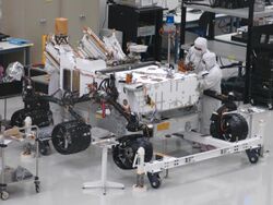
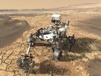
The rocker-bogie system is the suspension arrangement developed in 1988 for use in NASA's Mars rover Sojourner,[1][2][3] and which has since become NASA's favored design for rovers.[4] It has been used in the 2003 Mars Exploration Rover mission robots Spirit and Opportunity,[5] on the 2012 Mars Science Laboratory (MSL) mission's rover Curiosity,[6] the Mars 2020 rover Perseverance[7] and ISRO's Chandrayaan-3 rover Pragyan in 2023.
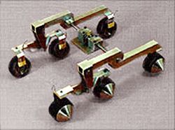
The "rocker" part of the suspension comes from the rocking aspect of the larger, body-mounted linkage on each side of the rover. These rockers are connected to each other and the vehicle chassis through a differential. Relative to the chassis, the rockers will rotate in opposite directions to maintain approximately equal wheel contact. The chassis maintains the average pitch angle of both rockers. One end of a rocker is fitted with a drive wheel, and the other end is pivoted to the bogie.
The "bogie" part of the suspension refers to the smaller linkage that pivots to the rocker in the middle and which has a drive wheel at each end. Bogies were commonly used as load wheels in the tracks of army tanks as idlers distributing the load over the terrain, and were also quite commonly used in trailers of semi-trailer trucks. Both tanks and semi-trailers now prefer trailing arm suspensions.
On the Sojourner rover the front wheels attach to the bogies, while on the MER and MSL rovers the front wheels attach to the rockers.
Design
The rocker-bogie design is unsprung and uses split rather than full-width axles, allowing the rover to climb over obstacles (such as rocks) that are up to twice the wheel's diameter in size while keeping all six wheels on the ground.[8] As with any suspension system, the tilt stability is limited by the height of the center of gravity. Systems using springs tend to tip more easily as the loaded side yields. Based on the center of mass, the Curiosity rover of the Mars Science Laboratory mission can withstand a tilt of at least 45 degrees in any direction without overturning, but automatic sensors limit the rover from exceeding 30 degree tilts.[9] The system is designed to be used at slow speed of around 10 centimetres per second (3.9 in/s) so as to minimize dynamic shocks and consequential damage to the vehicle when surmounting sizable obstacles.
The Jet Propulsion Laboratory states that this rocker bogie system reduces the motion of the main MER vehicle body by half compared to other suspension systems.[citation needed] Each of the Curiosity rover's six wheels has an independent motor.[10] The two front and two rear wheels have individual steering motors which allow the vehicle to turn in place. Each wheel also has grousers, providing grip for climbing in soft sand and scrambling over rocks.[11] The maximum speed of the robots operated in this way is limited to eliminate as many dynamic effects as possible so that the motors can be geared down, thus enabling each wheel to individually lift a large portion of the entire vehicle's mass.
In order to go over a vertical obstacle face, the front wheels are forced against the obstacle by the center and rear wheels. The rotation of the front wheel then lifts the front of the vehicle up and over the obstacle. The middle wheel is then pressed against the obstacle by the rear wheels and pulled against the obstacle by the front until it is lifted up and over. Finally, the rear wheel is pulled over the obstacle by the front two wheels. During each wheel's traversal of the obstacle, forward progress of the vehicle is slowed or completely halted. This is not an issue for the operational speeds at which these vehicles have been operated to date.
One of the future applications of rovers will be to assist astronauts during surface operations. To be a useful assistant, the rover will need to be able to move at least as fast as human walking speed. Other missions which have been proposed, such as the Sun-Synchronous Lunar Polar Rover, require even greater speeds (4–10 km/h).
See also
References
- ↑ Donald B. Bickler, "Articulated suspension system", US patent 4840394, published 1988-04-21, issued 1989-06-20, assigned to NASA
- ↑ NASA Patent Abstracts Bibliography, Section 1. Abstracts (Report). June 1990. p. 19. https://ntrs.nasa.gov/archive/nasa/casi.ntrs.nasa.gov/19900016382_1990016382.pdf.
- ↑ Bickler, Donald (April 1998). "Roving over Mars". Mechanical Engineering: 74–77. http://www.memagazine.org/backissues/membersonly/april98/features/mars/mars.html.
- ↑ Miller, David P.; Lee, Tze-Liang (March 17–21, 2002). "High-speed traversal of rough terrain using a rocker-bogie mobility system". Space 2002 and Robotics 2002. Albuquerque, NM. ISBN 0-7844-0625-1. http://dpm.kipr.org/papers/robotics02.pdf.
- ↑ "Rover Wheels". NASA. https://mars.nasa.gov/mer/mission/rover/wheels-and-legs/.
- ↑ "Wheels and Legs". NASA. https://mars.nasa.gov/msl/mission/rover/wheelslegs/.
- ↑ "Rover Wheels". NASA. https://mars.nasa.gov/mars2020/mission/rover/wheels/.
- ↑ https: https://commons.wikimedia.org/wiki/File:Wiki1Rocker-bogie_mechanism_animation.gif Reina, Giulio (2013). "On the Mobility of All-terrain Rovers". Industrial Robot 40 (2): 121–131. doi:10.1108/01439911311297720.
- ↑ Makovsky, Andre; Ilott, Peter; Taylor, Jim (November 2009). "Mars Science Laboratory Telecommunications System Design". Jet Propulsion Laboratory. http://descanso.jpl.nasa.gov/DPSummary/Descanso14_MSL_Telecom.pdf.
- ↑ Gross, Michael A.; Cardell, Greg (June 6, 2011). "An overview of NASA's Mars Science Laboratory". 9th European Space Power Conference (ESPC). Sainta Raphael, France. https://trs.jpl.nasa.gov/bitstream/handle/2014/42086/11-1313.pdf.
- ↑ "An Algorithm Helps Protect Mars Curiosity's Wheels" (in en-US). https://www.jpl.nasa.gov/news/an-algorithm-helps-protect-mars-curiositys-wheels.
 |


