3 21 polytope
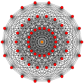 321 |
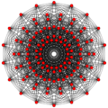 231 |
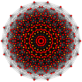 132 | |||
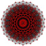 Rectified 321 |
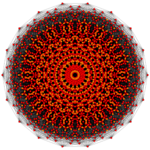 birectified 321 | ||||
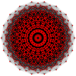 Rectified 231 |
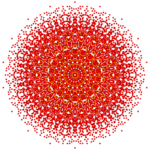 Rectified 132 | ||||
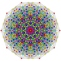
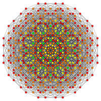
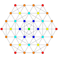
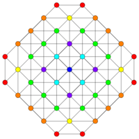
| Orthogonal projections in E7 Coxeter plane | |||||
|---|---|---|---|---|---|
In 7-dimensional geometry, the 321 polytope is a uniform 7-polytope, constructed within the symmetry of the E7 group. It was discovered by Thorold Gosset, published in his 1900 paper. He called it an 7-ic semi-regular figure.[1]
Its Coxeter symbol is 321, describing its bifurcating Coxeter-Dynkin diagram, with a single ring on the end of one of the 3-node sequences.
The rectified 321 is constructed by points at the mid-edges of the 321. The birectified 321 is constructed by points at the triangle face centers of the 321. The trirectified 321 is constructed by points at the tetrahedral centers of the 321, and is the same as the rectified 132.
These polytopes are part of a family of 127 (27-1) convex uniform polytopes in 7-dimensions, made of uniform 6-polytope facets and vertex figures, defined by all permutations of rings in this Coxeter-Dynkin diagram: ![]()
![]()
![]()
![]()
![]()
![]()
![]()
![]()
![]()
![]()
![]() .
.
321 polytope
| 321 polytope | |
|---|---|
| Type | Uniform 7-polytope |
| Family | k21 polytope |
| Schläfli symbol | {3,3,3,32,1} |
| Coxeter symbol | 321 |
| Coxeter diagram | |
| 6-faces | 702 total: 126 311 576 {35} |
| 5-faces | 6048: 4032 {34} 2016 {34} |
| 4-faces | 12096 {33} |
| Cells | 10080 {3,3} |
| Faces | 4032 {3} |
| Edges | 756 |
| Vertices | 56 |
| Vertex figure | 221 polytope |
| Petrie polygon | octadecagon |
| Coxeter group | E7, [33,2,1], order 2903040 |
| Properties | convex |
In 7-dimensional geometry, the 321 polytope is a uniform polytope. It has 56 vertices, and 702 facets: 126 311 and 576 6-simplexes.
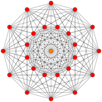
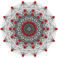
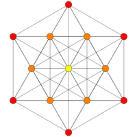
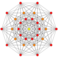
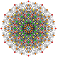
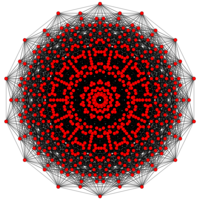
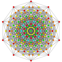
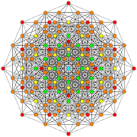
For visualization this 7-dimensional polytope is often displayed in a special skewed orthographic projection direction that fits its 56 vertices within an 18-gonal regular polygon (called a Petrie polygon). Its 756 edges are drawn between 3 rings of 18 vertices, and 2 vertices in the center. Specific higher elements (faces, cells, etc.) can also be extracted and drawn on this projection.
The 1-skeleton of the 321 polytope is the Gosset graph.
This polytope, along with the 7-simplex, can tessellate 7-dimensional space, represented by 331 and Coxeter-Dynkin diagram: ![]()
![]()
![]()
![]()
![]()
![]()
![]()
![]()
![]() .
.
Alternate names
- It is also called the Hess polytope for Edmund Hess who first discovered it.
- It was enumerated by Thorold Gosset in his 1900 paper. He called it an 7-ic semi-regular figure.[1]
- E. L. Elte named it V56 (for its 56 vertices) in his 1912 listing of semiregular polytopes.[2]
- H.S.M. Coxeter called it 321 due to its bifurcating Coxeter-Dynkin diagram, having 3 branches of length 3, 2, and 1, and having a single ring on the final node of the 3 branch.
- Hecatonicosihexa-pentacosiheptacontihexa-exon (Acronym Naq) - 126-576 facetted polyexon (Jonathan Bowers)[3]
Coordinates
The 56 vertices can be most simply represented in 8-dimensional space, obtained by the 28 permutations of the coordinates and their opposite:
- ± (-3, -3, 1, 1, 1, 1, 1, 1)
Construction
Its construction is based on the E7 group. Coxeter named it as 321 by its bifurcating Coxeter-Dynkin diagram, with a single ring on the end of the 3-node sequence.
The facet information can be extracted from its Coxeter-Dynkin diagram, ![]()
![]()
![]()
![]()
![]()
![]()
![]()
![]()
![]()
![]()
![]() .
.
Removing the node on the short branch leaves the 6-simplex, ![]()
![]()
![]()
![]()
![]()
![]()
![]()
![]()
![]()
![]()
![]() .
.
Removing the node on the end of the 2-length branch leaves the 6-orthoplex in its alternated form: 311, ![]()
![]()
![]()
![]()
![]()
![]()
![]()
![]()
![]() .
.
Every simplex facet touches a 6-orthoplex facet, while alternate facets of the orthoplex touch either a simplex or another orthoplex.
The vertex figure is determined by removing the ringed node and ringing the neighboring node. This makes 221 polytope, ![]()
![]()
![]()
![]()
![]()
![]()
![]()
![]()
![]() .
.
Seen in a configuration matrix, the element counts can be derived by mirror removal and ratios of Coxeter group orders.[4]
| E7 | k-face | fk | f0 | f1 | f2 | f3 | f4 | f5 | f6 | k-figures | notes | |||
|---|---|---|---|---|---|---|---|---|---|---|---|---|---|---|
| E6 | ( ) | f0 | 56 | 27 | 216 | 720 | 1080 | 432 | 216 | 72 | 27 | 221 | E7/E6 = 72x8!/72x6! = 56 | |
| D5A1 | { } | f1 | 2 | 756 | 16 | 80 | 160 | 80 | 40 | 16 | 10 | 5-demicube | E7/D5A1 = 72x8!/16/5!/2 = 756 | |
| A4A2 | {3} | f2 | 3 | 3 | 4032 | 10 | 30 | 20 | 10 | 5 | 5 | rectified 5-cell | E7/A4A2 = 72x8!/5!/2 = 4032 | |
| A3A2A1 | {3,3} | f3 | 4 | 6 | 4 | 10080 | 6 | 6 | 3 | 2 | 3 | triangular prism | E7/A3A2A1 = 72x8!/4!/3!/2 = 10080 | |
| A4A1 | {3,3,3} | f4 | 5 | 10 | 10 | 5 | 12096 | 2 | 1 | 1 | 2 | isosceles triangle | E7/A4A1 = 72x8!/5!/2 = 12096 | |
| A5A1 | {3,3,3,3} | f5 | 6 | 15 | 20 | 15 | 6 | 4032 | * | 1 | 1 | { } | E7/A5A1 = 72x8!/6!/2 = 4032 | |
| A5 | 6 | 15 | 20 | 15 | 6 | * | 2016 | 0 | 2 | E7/A5 = 72x8!/6! = 2016 | ||||
| A6 | {3,3,3,3,3} | f6 | 7 | 21 | 35 | 35 | 21 | 10 | 0 | 576 | * | ( ) | E7/A6 = 72x8!/7! = 576 | |
| D6 | {3,3,3,3,4} | 12 | 60 | 160 | 240 | 192 | 32 | 32 | * | 126 | E7/D6 = 72x8!/32/6! = 126 | |||
Images
| E7 | E6 / F4 | B7 / A6 |
|---|---|---|
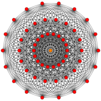 [18] |
 [12] |
 [7x2] |
| A5 | D7 / B6 | D6 / B5 |
 [6] |
 [12/2] |
 [10] |
| D5 / B4 / A4 | D4 / B3 / A2 / G2 | D3 / B2 / A3 |
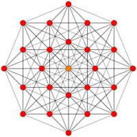 [8] |
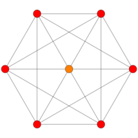 [6] |
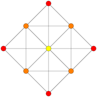 [4] |
Related polytopes
The 321 is fifth in a dimensional series of semiregular polytopes. Each progressive uniform polytope is constructed vertex figure of the previous polytope. Thorold Gosset identified this series in 1900 as containing all regular polytope facets, containing all simplexes and orthoplexes.
It is in a dimensional series of uniform polytopes and honeycombs, expressed by Coxeter as 3k1 series. (A degenerate 4-dimensional case exists as 3-sphere tiling, a tetrahedral hosohedron.)
Rectified 321 polytope
| Rectified 321 polytope | |
|---|---|
| Type | Uniform 7-polytope |
| Schläfli symbol | t1{3,3,3,32,1} |
| Coxeter symbol | t1(321) |
| Coxeter diagram | |
| 6-faces | 758 |
| 5-faces | 44352 |
| 4-faces | 70560 |
| Cells | 48384 |
| Faces | 11592 |
| Edges | 12096 |
| Vertices | 756 |
| Vertex figure | 5-demicube prism |
| Petrie polygon | octadecagon |
| Coxeter group | E7, [33,2,1], order 2903040 |
| Properties | convex |
Alternate names
- Rectified hecatonicosihexa-pentacosiheptacontihexa-exon as a rectified 126-576 facetted polyexon (acronym ranq) (Jonathan Bowers)[5]
Construction
Its construction is based on the E7 group. Coxeter named it as 321 by its bifurcating Coxeter-Dynkin diagram, with a single node on the end of the 3-node sequence.
The facet information can be extracted from its Coxeter-Dynkin diagram, ![]()
![]()
![]()
![]()
![]()
![]()
![]()
![]()
![]()
![]()
![]() .
.
Removing the node on the short branch leaves the 6-simplex, ![]()
![]()
![]()
![]()
![]()
![]()
![]()
![]()
![]()
![]()
![]() .
.
Removing the node on the end of the 2-length branch leaves the rectified 6-orthoplex in its alternated form: t1311, ![]()
![]()
![]()
![]()
![]()
![]()
![]()
![]()
![]() .
.
Removing the node on the end of the 3-length branch leaves the 221, ![]()
![]()
![]()
![]()
![]()
![]()
![]()
![]()
![]() .
.
The vertex figure is determined by removing the ringed node and ringing the neighboring node. This makes 5-demicube prism, ![]()
![]()
![]()
![]()
![]()
![]()
![]()
![]()
![]() .
.
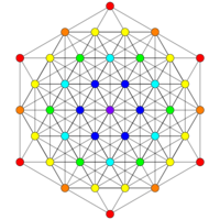
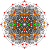
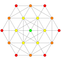
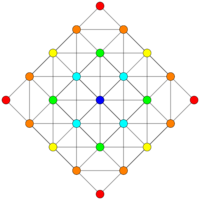
Images
| E7 | E6 / F4 | B7 / A6 |
|---|---|---|
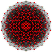 [18] |
 [12] |
 [7x2] |
| A5 | D7 / B6 | D6 / B5 |
 [6] |
 [12/2] |
 [10] |
| D5 / B4 / A4 | D4 / B3 / A2 / G2 | D3 / B2 / A3 |
 [8] |
 [6] |
 [4] |
Birectified 321 polytope
| Birectified 321 polytope | |
|---|---|
| Type | Uniform 7-polytope |
| Schläfli symbol | t2{3,3,3,32,1} |
| Coxeter symbol | t2(321) |
| Coxeter diagram | |
| 6-faces | 758 |
| 5-faces | 12348 |
| 4-faces | 68040 |
| Cells | 161280 |
| Faces | 161280 |
| Edges | 60480 |
| Vertices | 4032 |
| Vertex figure | 5-cell-triangle duoprism |
| Petrie polygon | octadecagon |
| Coxeter group | E7, [33,2,1], order 2903040 |
| Properties | convex |
Alternate names
- Birectified hecatonicosihexa-pentacosiheptacontihexa-exon as a birectified 126-576 facetted polyexon (acronym branq) (Jonathan Bowers)[6]
Construction
Its construction is based on the E7 group. Coxeter named it as 321 by its bifurcating Coxeter-Dynkin diagram, with a single node on the end of the 3-node sequence.
The facet information can be extracted from its Coxeter-Dynkin diagram, ![]()
![]()
![]()
![]()
![]()
![]()
![]()
![]()
![]()
![]()
![]() .
.
Removing the node on the short branch leaves the birectified 6-simplex, ![]()
![]()
![]()
![]()
![]()
![]()
![]()
![]()
![]()
![]()
![]() .
.
Removing the node on the end of the 2-length branch leaves the birectified 6-orthoplex in its alternated form: t2(311), ![]()
![]()
![]()
![]()
![]()
![]()
![]()
![]()
![]() .
.
Removing the node on the end of the 3-length branch leaves the rectified 221 polytope in its alternated form: t1(221), ![]()
![]()
![]()
![]()
![]()
![]()
![]()
![]()
![]() .
.
The vertex figure is determined by removing the ringed node and ringing the neighboring node. This makes rectified 5-cell-triangle duoprism, ![]()
![]()
![]()
![]()
![]()
![]()
![]()
![]()
![]() .
.
Images
| E7 | E6 / F4 | B7 / A6 |
|---|---|---|
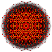 [18] |
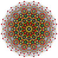 [12] |
 [7x2] |
| A5 | D7 / B6 | D6 / B5 |
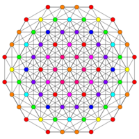 [6] |
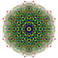 [12/2] |
 [10] |
| D5 / B4 / A4 | D4 / B3 / A2 / G2 | D3 / B2 / A3 |
 [8] |
 [6] |
 [4] |
See also
- List of E7 polytopes
Notes
References
- T. Gosset: On the Regular and Semi-Regular Figures in Space of n Dimensions, Messenger of Mathematics, Macmillan, 1900
- Elte, E. L. (1912), The Semiregular Polytopes of the Hyperspaces, Groningen: University of Groningen
- H.S.M. Coxeter, Regular Polytopes, 3rd Edition, Dover New York, 1973
- Kaleidoscopes: Selected Writings of H.S.M. Coxeter, edited by F. Arthur Sherk, Peter McMullen, Anthony C. Thompson, Asia Ivic Weiss, Wiley-Interscience Publication, 1995, ISBN:978-0-471-01003-6 [1]
- (Paper 24) H.S.M. Coxeter, Regular and Semi-Regular Polytopes III, [Math. Zeit. 200 (1988) 3-45] See p342 (figure 3.7c) by Peter mcMullen: (18-gonal node-edge graph of 321)
- Klitzing, Richard. "7D uniform polytopes (polyexa)". https://bendwavy.org/klitzing/dimensions/polyexa.htm. o3o3o3o *c3o3o3x - naq, o3o3o3o *c3o3x3o - ranq, o3o3o3o *c3x3o3o - branq
External links
- Gosset’s Polytopes in vZome
Fundamental convex regular and uniform polytopes in dimensions 2–10
| ||||||||||||
|---|---|---|---|---|---|---|---|---|---|---|---|---|
| Family | An | Bn | I2(p) / Dn | E6 / E7 / E8 / F4 / G2 | Hn | |||||||
| Regular polygon | Triangle | Square | p-gon | Hexagon | Pentagon | |||||||
| Uniform polyhedron | Tetrahedron | Octahedron • Cube | Demicube | Dodecahedron • Icosahedron | ||||||||
| Uniform 4-polytope | 5-cell | 16-cell • Tesseract | Demitesseract | 24-cell | 120-cell • 600-cell | |||||||
| Uniform 5-polytope | 5-simplex | 5-orthoplex • 5-cube | 5-demicube | |||||||||
| Uniform 6-polytope | 6-simplex | 6-orthoplex • 6-cube | 6-demicube | 122 • 221 | ||||||||
| Uniform 7-polytope | 7-simplex | 7-orthoplex • 7-cube | 7-demicube | 132 • 231 • 321 | ||||||||
| Uniform 8-polytope | 8-simplex | 8-orthoplex • 8-cube | 8-demicube | 142 • 241 • 421 | ||||||||
| Uniform 9-polytope | 9-simplex | 9-orthoplex • 9-cube | 9-demicube | |||||||||
| Uniform 10-polytope | 10-simplex | 10-orthoplex • 10-cube | 10-demicube | |||||||||
| Uniform n-polytope | n-simplex | n-orthoplex • n-cube | n-demicube | 1k2 • 2k1 • k21 | n-pentagonal polytope | |||||||
| Topics: Polytope families • Regular polytope • List of regular polytopes and compounds | ||||||||||||
 |

